
Decreasing intermod on the Kenwood TM-733 receivers
In FM receivers, stronger signals typically result in less noise. Sensitivity measurements often use a standard 1 kHz tone at a deviation of 3 kHz, with the SINAD ratio measuring the tone against background noise. A 12 dB SINAD indicates the minimum signal strength required for intelligible reception, although it may still be noisy. The relationship between signal strength and intermodulation is such that reducing the strength of interfering signals by 1 dB can decrease intermod products by about 3 dB. However, this rule does not apply to image response issues.
The TM-733A contains multiple RF amplifier stages, and once the intrinsic noise of the RF amplifier exceeds the noise of the mixer, further amplification does not improve signal quality and can exacerbate intermodulation susceptibility. Sensitivity tests before and after modifications indicated that placing attenuation after the first RF amplifier stage could effectively reduce signal levels to the mixer without significantly impacting overall sensitivity. It was noted that the actual sensitivity of the radio might exceed published specifications, allowing for adjustments to maintain performance within original limits. The mixer stage is often the primary contributor to intermod problems, although any amplification stage can contribute to the issue.
In designing a schematic for the Kenwood TM-733A, the following key elements should be included:
1. **Power Supply Circuit**: This section should provide stable voltage and current to the radio, ensuring that the dual-band transmitter operates effectively at 50 watts (VHF) and 35 watts (UHF).
2. **RF Amplifier Stages**: Multiple RF amplifier stages should be incorporated to boost the incoming signals while considering the trade-off between amplification and noise. Careful design is necessary to prevent excessive gain that could lead to intermodulation distortion.
3. **Mixer Stage**: The mixer stage is crucial for converting RF signals to intermediate frequencies. Its design must minimize noise while ensuring that intermodulation products are kept to a minimum.
4. **Attenuation Circuit**: An attenuation circuit should be implemented following the first RF amplifier stage. This circuit will help manage signal levels before they reach the mixer, effectively reducing potential intermodulation issues without sacrificing overall sensitivity.
5. **Demodulation Circuit**: This section will decode the received signals, converting them back into audio frequencies for output.
6. **Control Interface**: A user-friendly interface should be included to facilitate operation, allowing users to adjust settings such as frequency selection, power output, and other operational parameters.
7. **Filtering**: Appropriate bandpass filters should be employed to ensure that only the desired frequencies are processed, further reducing the likelihood of intermodulation distortion.
8. **Output Stage**: The final output stage must be designed to deliver the specified power levels to the antenna while maintaining signal integrity and minimizing distortion.
Each component of the schematic must be carefully designed to balance performance with sensitivity, ensuring that the TM-733A operates effectively in various environments while minimizing interference from unwanted signals.The Kenwood TM-733A is an older dual-band mobile radio. This radio is capable of 50 watts transmit on VHF, 35 watts on UHF, full-duplex crossband repeat, and simultaneous receive on two VHF or UHF frequencies. It does have a problem, however: It is terribly sensitive to being overloaded by other signals. The effects of overload (or "intermod" - co mmonly referred to as IMD meaning "InterModulation Distortion") manifests itself as the reception of signals that aren`t really on frequency. During a `bout of intermod, one will often hear QSOs of other repeaters (amateur and not) as well as odd bleeps and buzzes from paging and telemetry systems.
Because intermod is a mix of multiple signals, you cannot experience it from just one signal - it takes at least two signals! Even before I got my own `733, I was aware of the problem: Back in early 90`s a friend of mine bought a TM-732 - the predecessor to the TM-733.
It had some pretty nice features and a reasonably intelligent (I thought) operator interface. But it had terrible intermod problems: It would seem to squeal and squawk at almost any time, anywhere due to front-end overload. He asked me to look into it and see if there was something that I could do about it. For an FM receiver, the stronger the signal, the less noisy it is. When quantifying sensitivity measurements, a common standard is to have a signal with a 1 KHz tone at a deviation of 3 KHz.
The "SINAD" is the ratio of that 1 KHz tone to the background noise. The "12 dB SINAD" measurement is how much signal is required to get that tone 12dB above the "popcorn" noise one hears on a weak FM signal. How noisy is a signal with 12dB of SINAD Pretty noisy - but if the other person is talking in a normal voice (i.
e. not quietly or far from the microphone) 12dB of SINAD is good enough that, although noisy, one doesn`t really have any problem understanding any of the words. When it comes to intermod, it (generally) follows a simple rule: Reduce the strength of the offending signal(s) by 1 dB, and the resulting intermod products will decrease by about 3 dB.
So, if you can reduce the amount of signal by, say, 6 dB, then the intermod will (theoretically) decrease by 18 dB. Note that if the interference problem is due to image response, then this rule does not hold - which makes sense, as an image problem is not the same is an IMD problem.
As it turns out, there are multiple RF amplifier stages in the TM-732 (and the `733. ) As with any receiver, once one has enough amplification for the intrinsic RF amplifier noise to exceed the noise of the mixer, the further amplification does no good: It simply amplifies the noise along with the original signal - it would be akin to turning up the volume on a noisy signal and not expecting the noise to get louder along with the desired signal! Worse than this, each dB of additional unnecessary gain can also unnecessarily increase intermod susceptibility by 3dB - more or less.
Table 1: This table shows the sensitivity of the "main" receiver portion of my TM-733 before and after modification. These readings were taken with the "AIP" (attenuation) off. With the AIP on, sensitivity on VHF and UHF was about 6db worse (i. e. about 0. 35 microvolts for 12 db SINAD in the amateur bands - see text. ) The trick was to put the attenuation after the first RF amplifier stage: Signal levels to the mixer could be decreased without reduction of overall sensitivity if one didn`t go overboard.
Also, I knew that the actual sensitivity of the radio was significantly higher than the published ratings - so I was willing to decrease sensitivity just to the point of being within the original specifications of the radio. It is worth mentioning that any stage of amplification in a receiver can contribute to intermod problems - but it is most likely to be the mixer stage that contributes the lion`s share of the problem: The amplifier stages are intended to be l
🔗 External reference
Related Circuits
The regen is basically an oscillator circuit with a gain control that allows the user to adjust the feedback to a point just below oscillation or, quite often, just above the critical level such that a small oscillation is...
Before using this or a similar device, their data sheet should be read carefully and any power supply recommendations should be followed to prevent false output pulses. The receiver module used for this test worked very well under all...
The intermodal servo preamplifier circuit operates at 115V and 60Hz, designed to provide a differential output for a servo motor amplifier. It features an inverting connection using an operational amplifier (op-amp), along with an additional op-amp configured to create...
This project originated from an interest in a new form of radio transmission known as Digital Radio Mondial (DRM). The Digital Radio Mondial (DRM) is a revolutionary digital broadcasting technology designed for AM and FM radio. It provides enhanced audio...
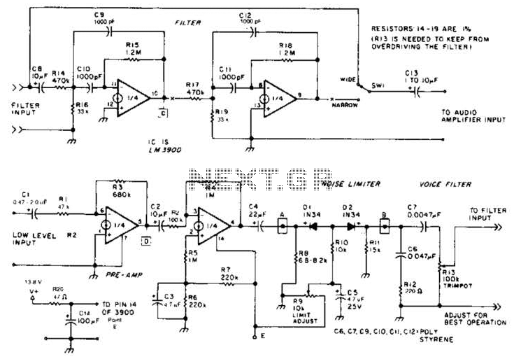
The noise limiter circuit features a preamplifier clipper and a switchable audio bandpass filter. Audio levels ranging from 5 to 50 mV are amplified in a preamplifier to several volts peak-to-peak, which are then sent to a clipper and...

The individual was not inclined to create and program the timing controller for the PCB laser printer. They recalled having a laser tag gun that had been misaligned during a previous disassembly. The device in question is a Nerf...
Warning: include(partials/cookie-banner.php): Failed to open stream: Permission denied in /var/www/html/nextgr/view-circuit.php on line 713
Warning: include(): Failed opening 'partials/cookie-banner.php' for inclusion (include_path='.:/usr/share/php') in /var/www/html/nextgr/view-circuit.php on line 713