
Delay Circuit

To design this delay circuit, a 555 timer IC in astable mode can be utilized. The 555 timer will generate a square wave output that can be configured to pulse the vibrational motor at the desired interval. The frequency of the output pulse can be determined by the resistor and capacitor values connected to the timer.
For the 0.75-second pulse interval, the frequency can be calculated using the formula:
\[ f = \frac{1.44}{(R1 + 2R2)C} \]
Where:
- \( f \) is the frequency in Hertz (Hz),
- \( R1 \) and \( R2 \) are the resistances in ohms,
- \( C \) is the capacitance in farads.
To achieve the required 0.75 seconds pulse, the output frequency should be set to approximately 1.33 Hz (since the period is the inverse of frequency). This can be achieved by selecting appropriate resistor and capacitor values.
For the adjustable delay feature, a potentiometer can be used in place of one of the resistors (R2). By adjusting the potentiometer, the timing can be varied, allowing the delay to be set anywhere between 4 to 10 seconds.
The vibrational motor can be connected to the output of the 555 timer, which will drive the motor on and off according to the generated pulse. A transistor may be used to switch the motor on and off, allowing for higher current handling than the 555 timer can provide directly.
The circuit can be powered by a 9-volt battery, ensuring that the voltage levels are compatible with the motor and the 555 timer. Proper decoupling capacitors should be placed close to the power pins of the 555 timer to ensure stability during operation.
In summary, the circuit will consist of a 555 timer configured in astable mode, a potentiometer for adjusting the delay, and a transistor to drive the vibrational motor, all powered by a 9-volt battery. This configuration will ensure reliable operation and the desired timing functionality.I need to make a small 4-10 second (changeable) delay circuit that pulses a cell phone vibrational motor every 0.75 seconds. I`m using a 9 volt battery. Could anyone.. 🔗 External reference
Related Circuits
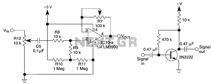
This circuit utilizes one-quarter of an LM3900 to create a simple variable-gain front end for an oscilloscope. R7 serves as the gain control. Additionally, a basic preamplifier is included for applications requiring more than 10X gain. The circuit employs the...

Short circuits in the tracks, points, or wiring are nearly unavoidable when constructing or operating a model railway. Although transformers for model systems are designed with built-in bimetallic switches to protect against short circuits, the response time of these...
The first reverberator presented is based on the TDA1022, which is the most commonly used BBD (Bucket Brigade Device). Adjustments for proper functionality of the reverberator are required before connecting the power supply. The TDA1022 is a versatile BBD that...
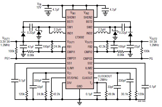
The LT3692 dual current mode PWM step-down DC-DC converter circuit, featuring two internal 3.5A switches, can be designed into a simple power supply circuit suitable for various electronic applications, such as distributed supply regulation or automotive circuits. The LT3692...
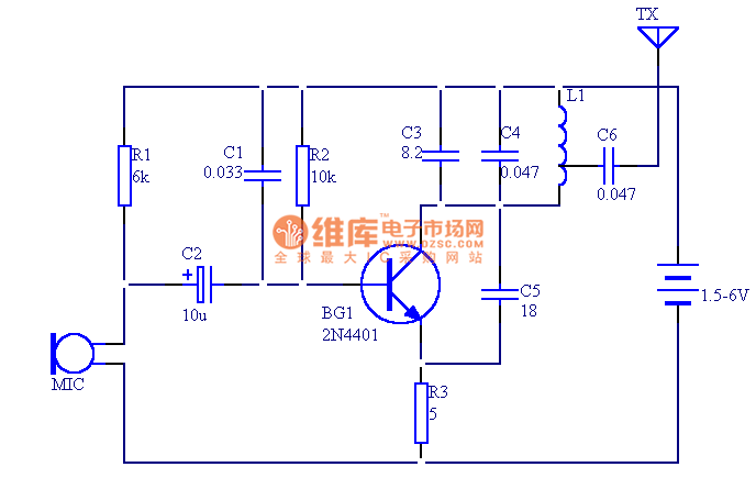
The circuit presented in this document utilizes 12 components to create a compact wireless FM microphone that operates with a stable frequency. The effective transmission range is approximately 30 meters, extending to over 100 meters when powered by a...

The schematic illustrates the design of a circuit that measures the resistance of the skin and transforms it into a functional switching signal. This circuit typically employs a resistive sensor, often referred to as a skin resistance sensor or galvanic...