
Delay switching for Loudspeaker
The circuit operates from an AC power source connected through connector J1. The primary voltage input is derived from a transformer rated at 2X12V AC, which may also be sourced from an existing 12V coil in a power amplifier or from the main supply coils of the final amplifier. The resistors R1, R2, and R3 are selected based on the voltage supplied to the amplifier, adhering to Ohm's law to manage voltage drops appropriately. The voltage at point A, prior to the voltage regulator IC2, must exceed +15V at 200mA, as IC2 is responsible for powering the relays and LEDs in the circuit.
The circuit's functionality is primarily governed by the charging of capacitor C6 through resistor R4 when powered by the AC mains (220V AC). The state of input pin of IC1a changes based on the voltage across C6, controlling the switching of transistor Q1 and relay RL1. Resistor RX ensures a safe connection between the transformer and the AC mains, protecting against fuse damage under high load conditions. After a delay of approximately one second, as C6 charges, the negative terminal reaches 0V, causing the input of IC1A to also drop to 0V. This transition allows Q1 to activate RL1, shorting RX and applying full mains voltage to the transformer while simultaneously illuminating LED LD1.
The circuit also includes a delay mechanism for charging capacitor C7 through resistor R5, which takes about five seconds. Once C7 reaches the required charge, the state of pin 5 on IC1b changes, enabling transistor Q2 to activate relay RL2, connecting the amplifier output to the loudspeakers. Concurrently, capacitor C8 charges through resistor R13 over a duration of approximately two seconds. When C8 is fully charged, transistor Q3 activates relay RL3, further ensuring the circuit is fully operational.
In the event of a power interruption, all supply voltages drop rapidly, resulting in the immediate disconnection of all relays and loudspeakers to prevent damage. The circuit is equipped with DC detection circuits at J2/1 and J2/4; if a continuous voltage is detected, transistors Q5 or Q6 will drive the input of IC1b to 0V, shutting down the output to transistors Q2 and Q3, thereby disconnecting the loudspeakers until the DC condition is resolved. Additionally, IC1D will activate a buzzer (BZ) and LED LD3 to signal an error condition, with the buzzer volume adjustable via trimmer TR1.
Component values may be modified, particularly capacitors C7 and C8, to alter timing characteristics. Resistors R1 and R2, along with R3 and R?, should be positioned away from the PCB due to heat generation. IC2 requires a heatsink when input voltage exceeds +15V. Special attention must be paid to the RX/CX circuit and RL1 contacts, as mains voltage poses a significant electrocution hazard; therefore, insulation and high-quality relays from reputable manufacturers are essential for safety.The supply of circuit becomes from a AC line in the J1. This voltage can be from a separate transformer 2X12V (the prices of materials that I give it is for 2X12V AC), from existing coil 12V in their M/T of power amplifier or if it cannot become somebody from the two, then from the coils of mainly supply final amplifier, adapting always the prices of resistances R1/2 and R3, proportionally the price of voltage that is supplied the amplifier, according to the law of Ohm and the fall of voltage that we want to achieve (R=V/i). The voltage that it should we have in point A, before the IC2, should is bigger than + 15V 200mA, the IC2 supplies all the relay and led.
The remainder circuit is supplied by the R3/D9. When we supply the amplifier with voltage of network (220V AC), charge the C6 via the R4, the price in the entry of IC1a is (H) exit (L) Q1- RL1, is in cutting off. In line with being first the M/T of power supply, intervenes the RX, which ensures smooth connection the M/T in the network, avoiding the burn of fuses, specifically if the force power supply, is big.
After 1sec after charge the C6, his negative pole goes to 0V, the entry of IC1A becomes 0V (L), conduct Q1 closes the RL1, short the resistance RX and all the voltage of network is applied in the M/T. Simultaneously turns on LD 1. Via the R5 charge slow the C7 (~5sec), when charge the situation in the pin5 of IC1b become (H), (the other are already (H) from the R23), exit is (L) and the exit of IC1C (H), the Q2 drive the RL2, giving the output of amplifiers in loudspeaker.
Simultaneously via the R13 charge the C8 (~2 sec). Hardly charge the C8, conduct the Q3 and close the contacts of RL3, at the same time with those of RL2. The circuit is in complete operation. If we interrupt the line of network all the supply?s fall very fast, with result all relay is cut off, very rapidly cut off, him loudspeakers.
If are presented some continuous voltage in entries J2/1 and J2/4, the two circuits of detection DC, then the Q5 or Q6 conduct and lead the entry of IC1b to pin 5 to 0V (L), with result the exit is become (H), the exit of IC1c to be become (L), transistors Q2-3 are cut off and away also the RL2-3 to open, disconnect, him loudspeakers, from the output of amplifiers, until is raised the cause of presence DC.. The same time the exit of IC1D, becomes (H), Q4 conduct, the buzzer [BZ] sounds and turns on the LD3, signaling error.
The intensity of sound of BZ, can be regulated from the TR1, but it can it is suppressed if we do not want sound clue of error. The prices of times can change, if are changed capacitors C7-8, with different capacity. Resistances R1-2 if use finally, R3 and R?, should be in some distance from pcb, one and likely hot. The IC2 should enter on heatsink, specifically if the voltage of entry exceeds the +15V. Big attention it should we give in the circuit round resistance RX/CX and the contacts of RL1, because the voltage of network is dangerous (DANGER of ELECTROCUTION).
For this reason good it is insulation. What it should we are careful is the quality of all relay, is very good and from known constructor. R1-2=See text* D1-4= 1N4007 R3=470R 1W*see text D5-8= 1N4148 R4-5= 1M D9=12V 1.2W Zener R6-7= 1K D10-22= 1N4148 R8-14= 15K LD1-2= LED R9-15= 56K LD3=Flash Led [RED] R10-16= 56K BZ= BUZZER 12V R11-17= 10K J1-4= Connectors R12-13= 39K TR1= 10K Trimmer R18= 39K RL1-3= 12V 2X2(10A)RELAY R19= 1K2 R20= 1K R21-22= 3K9 R23= 22K R24= 39K RX= 47R 10W C1= 220uF 63V C2-5= 47uF 63V C3-4=100nF C6= 1uF 25V C7= 4.7uF 25V C8= 470uF 16V C9-14= 22uF 16V C10-13= 33uF 63V CX= 33nF 630V IC1= 4093 cmos IC2= 7812T Q1-4= BD679 Q5-6= BC550C 🔗 External reference
Related Circuits
Introduction and disclaimer for individuals interested in a fading dome light (also referred to as courtesy light or theatre lighting) without incurring high costs. A fading dome light circuit is designed to create a gradual illumination effect, enhancing the aesthetic...
Here's a power-on time delay relay circuit that takes advantage of the emitter/base breakdown voltage of an ordinary bi-polar transistor. The reverse connected emitter/base junction of a 2N3904 transistor is used as an 8 volt zener diode which creates...
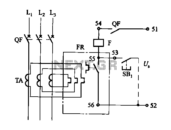
The DK-5A, 5D, and SDb control boxes are equipped with a thermal electromagnetic overcurrent release, as depicted in Figure 6-80. The trip mechanism provides both overload and instantaneous short circuit protection with a long delay feature. In the figure,...
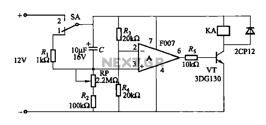
A delay circuit utilizing an operational amplifier functions as a comparator, providing high timing accuracy. The timer's delay range is from 1 to 30 seconds. The delay time is determined by resistors Ri, RP, and capacitor C. By adjusting...

Four high-level inputs, double bar switching. This module can be a necessary addition to the Modular Preamplifier Control Center when more than two sources are required. The described circuit module serves as an interface for connecting multiple audio sources to...
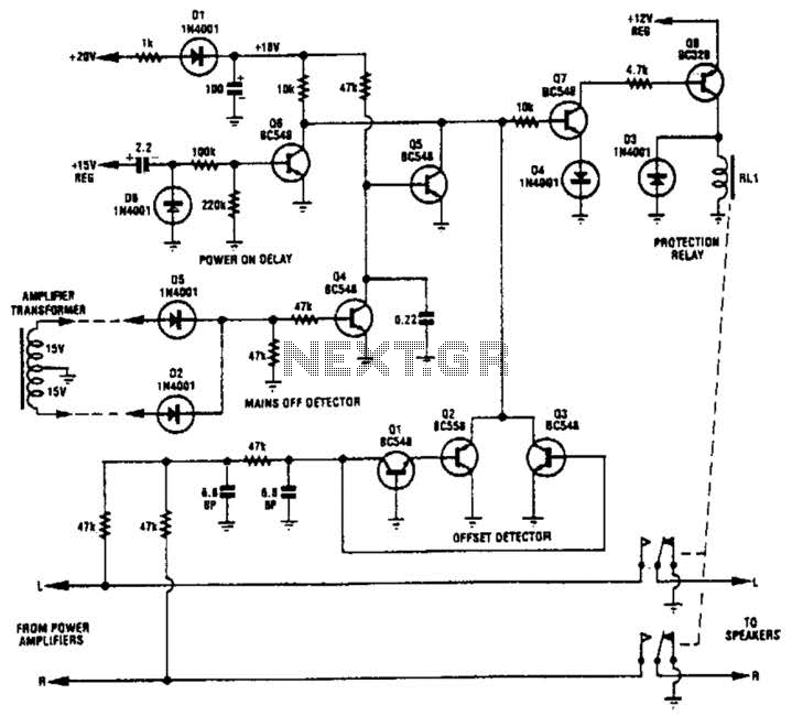
Transistors Q1, Q2, and Q3 monitor the two outputs of the stereo amplifier. If the offsets exceed 2 V, Q7 is turned off, which in turn deactivates Q8 and the normally on relay. Diodes D2 and D5, along with...
Warning: include(partials/cookie-banner.php): Failed to open stream: Permission denied in /var/www/html/nextgr/view-circuit.php on line 713
Warning: include(): Failed opening 'partials/cookie-banner.php' for inclusion (include_path='.:/usr/share/php') in /var/www/html/nextgr/view-circuit.php on line 713