
Deluxe Radar Detector
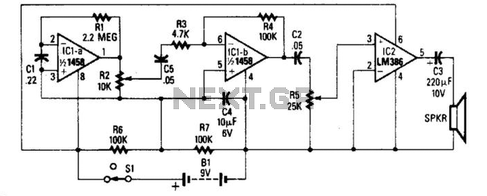
The radar detector circuit primarily consists of an operational amplifier (op-amp), which functions as the core component for detecting microwave signals. The op-amp is configured in a manner that allows it to amplify the weak microwave signals received by the antenna. The circuit typically includes an antenna designed to capture microwave frequencies, which are then fed into the input of the op-amp.
The output from the op-amp is connected to an audio amplifier stage, which is responsible for driving a loudspeaker. This audio amplifier can be a simple transistor-based amplifier or an integrated circuit designed for audio applications. The amplified audio signal is then sent to the loudspeaker, producing a sound that indicates the presence of microwave signals.
To ensure optimal performance, the circuit may include additional components such as resistors and capacitors that set the gain of the op-amp and filter out unwanted noise. Power supply considerations are also crucial; the circuit requires a stable voltage source to ensure proper operation of the op-amp and audio amplifier.
Overall, this radar detector design allows for effective detection of microwave signals, providing audible alerts through the loudspeaker, which can be particularly useful in various applications such as speed detection in law enforcement or monitoring in industrial settings. This simple radar detector includes an audio amplifier for driving a loud speaker. As in Fig. 69-1, it uses an op amp as a detector of microwave signals. 🔗 External reference
Related Circuits
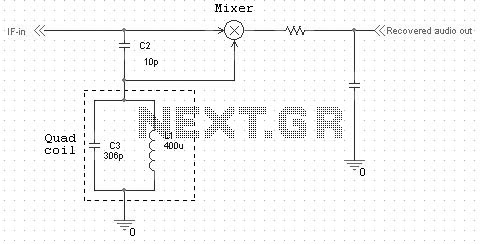
Quadrature FM detectors use a high-reactance capacitor (C2) to produce two signals with a 90 degree phase difference. The phase-shifted signal is then applied to an LC-tuned resonant at the carrier frequency (L1 and C3). Frequency changes will then...
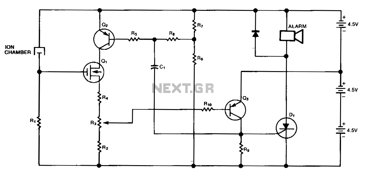
This circuit originates from U.S. Patent 3,778,800, awarded to BRK Electronics in Aurora, IL. It provides a smoke detector equipped with an alarm system for both smoke detection and low battery indication. The R6/R7 voltage divider monitors the battery...
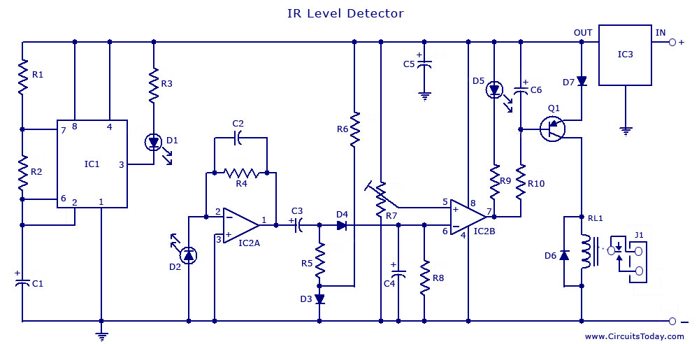
An infrared (IR) sensor or detector circuit diagram utilizing a 555 integrated circuit (IC), primarily employed as a water level or liquid level sensor and proximity detector circuit. The described circuit employs a 555 timer IC configured in a monostable...
This rain detector alerts users immediately when it starts to rain, providing enough time to close windows and secure belongings. The battery-operated circuit consumes minimal current when the sensor is dry and maintains low current consumption when the buzzer...
The circuit diagram of the Lie Detector consists of three transistors (TR1 to TR3), a capacitor (C1), two LEDs (L1 & L2), five resistors (R1 to R5), and a variable resistor (VR1). Suitable transistors include BC547, BC548, or BC549,...
The TRF1115 is the first of two ASICs utilized in the receiver section of the Texas Instruments MMDS/MDS/WCS/802.16x chipset. This device is responsible for down-converting the input frequency to an intermediate frequency (IF) within the range of 420 MHz...