Demodulation Techniques
1. Definition of Demodulation
1.1 Definition of Demodulation
Demodulation is the essential process of extracting the original information-bearing signal from a modulated carrier wave. This technique is crucial in the field of communications, enabling the transmission and reception of multimedia content, from digital data to voice signals. The modulation itself is the process of altering one or more properties of the carrier wave—such as its amplitude, frequency, or phase—in accordance with the information signal. Thus, demodulation serves as the inverse function of modulation, ensuring that the conveyed information can be accurately extracted and understood at the receiver's end.
Throughout the history of telecommunications, various demodulation techniques have been developed to meet the demands of high fidelity and bandwidth efficiency in diverse applications. With the proliferation of wireless communication technologies—including mobile networks, satellite communication, and digital broadcast systems—an in-depth understanding of demodulation principles and methods has become indispensable for engineers and researchers alike.
One of the most fundamental aspects of demodulation lies in the technique itself. To grasp the demodulation process, it is beneficial to consider the raw mathematical representation of the signals involved:
Let's denote the modulated signal as:
Where:
- s(t) – the modulated signal
- A_c – amplitude of the carrier wave
- f_c – frequency of the carrier wave
- \phi(t) – phase modulating the carrier as a function of time
To demodulate this signal involves retrieving the phase information \(\phi(t)\) from the received signal. This can be performed using various techniques such as:
- Envelope Detection – Primarily used for amplitude modulation (AM), where the envelope of the signal is detected to retrieve the original information.
- Coherent Detection – A method that requires the receiver to have information about the phase and frequency of the carrier wave, commonly used in phase shift keying (PSK).
- Frequency Discrimination – Used in frequency modulation (FM), where changes in frequency correlate with the information signal amplitude.
- Pulse Code Demodulation – Applied in digital communication, where discrete signal values are demodulated to retrieve the original digital data.
Each of these techniques utilizes different approaches to reconstruct the original information-bearing signal, highlighting the importance of understanding the nature of the modulated signal and the constraints imposed by the communication environment.
The practical implications of effective demodulation techniques are vast. For instance, in mobile communication systems, robust demodulation methods enhance the reliability of voice calls and data transmission, improving the user experience. In satellite communications, accurate demodulation allows for the transmission of high-definition video and other bandwidth-intensive applications. Furthermore, as we transition to more complex digital modulation schemes in modern communication systems, the study of these techniques remains a significant area of research and development.
1.2 Importance in Communication Systems
Demodulation techniques play a crucial role in modern communication systems, where the transmission and reception of information rely on converting modulated signals back into their original form. The essence of demodulation lies in its ability to extract meaningful data from complex waveforms that have been altered for effective transmission over varying media. This section delves into the significance of demodulation, emphasizing its impact on performance metrics in communication networks.
At its core, demodulation is essential for enabling the receiver to decode the information that was encoded by the transmitter. Without effective demodulation algorithms, communication systems would struggle with high error rates, resulting in unreliable data exchange. In this context, we examine various demodulation techniques and their practical relevance, which can significantly influence overall system performance in terms of bandwidth efficiency, power consumption, and data integrity.
Understanding the Spectrum of Demodulation Techniques
Demodulation techniques can be broadly categorized based on the modulation schemes employed, such as Amplitude Modulation (AM), Frequency Modulation (FM), and Phase Shift Keying (PSK). Each technique has unique characteristics, and selecting the appropriate demodulation approach is key to optimizing performance.
For instance, in amplitude modulation systems, the envelope detection method is frequently employed. This technique involves rectifying the received signal and filtering it to retrieve the original information. In contrast, frequency modulation often utilizes techniques such as phase-locked loops (PLLs) for demodulation. Understanding these distinctions enables engineers to tailor their communication systems effectively, ensuring that the chosen demodulation method complements the modulation used.
Practical Relevance in Real-World Applications
In practical terms, demodulation is vital across a variety of applications, ranging from telecommunications to broadcasting and satellite communications. For example, in satellite communications, where signals must traverse vast distances, effective demodulation can help mitigate the effects of noise and distortion introduced in the propagation medium. This is achieved through techniques such as Differential Phase Shift Keying (DPSK), which offers resilience against common errors encountered in long-distance signal transmission.
Moreover, the burgeoning field of Internet of Things (IoT) devices underscores the importance of robust demodulation strategies. As millions of devices transmit data wirelessly, efficient demodulation techniques become essential for ensuring high throughput and low latency, critical for applications like real-time monitoring and automation systems.
Additionally, the evolution of digital communication standards, including 5G and beyond, highlights the continued innovation in demodulation methods. Advanced techniques such as Orthogonal Frequency Division Multiplexing (OFDM) leverage sophisticated demodulation to enhance spectral efficiency, accommodating the increasing demand for higher data rates and improved quality of service.
The Path Forward: Challenges and Innovations
Despite the advancements in demodulation techniques, challenges remain. Issues such as multipath fading, noise, and interference necessitate ongoing research and development. Engineers and scientists continually seek new algorithms and methodologies to enhance demodulation performance under adverse conditions. Techniques like machine learning have started to show promise in optimizing demodulation processes, allowing for adaptive systems that learn and improve based on evolving signal environments.
In summary, demodulation techniques are integral to the functionality and success of communication systems. Their ability to accurately retrieve transmitted information not only affects data integrity but also influences bandwidth utilization and overall system performance. As communication technologies continue to advance, the relevance of effective demodulation will only become more pronounced, driving further innovation in this vital field.
2. Amplitude Demodulation
2.1 Amplitude Demodulation
Amplitude demodulation is a fundamental technique in signal processing, primarily used to extract information from amplitude-modulated (AM) signals. By understanding the underlying principles of this technique, engineers and researchers can develop better communication systems, including radio broadcasting and satellite communications.
Understanding Amplitude Modulation
Before delving into demodulation, it's vital to grasp the concept of amplitude modulation itself. In amplitude modulation, the amplitude of a carrier wave is varied in proportion to the instantaneous amplitude of the modulating signal, which can be a voice, music, or data signal. The mathematical representation of an AM signal is expressed as:
Here, \(s(t)\) represents the modulated signal, \(A\) is the carrier amplitude, \(m(t)\) is the modulating message signal, and \(f_c\) is the carrier frequency.
Basic Principles of Amplitude Demodulation
Demodulation involves the process of reversing modulation, extracting the original message signal \(m(t)\) from the modulated carrier signal \(s(t)\). One of the simplest and most prevalent methods for AM demodulation is known as envelope detection.
Envelope Detection
The envelope detection technique relies on the fact that the amplitude of the AM signal contains the original message signal's information. To perform envelope detection, the following steps are generally implemented:
- Rectification: The received AM signal is first passed through a diode that allows only one half of the waveform to be processed, effectively converting it into a unidirectional signal.
- Smoothing: The rectified signal is then filtered using a low-pass filter. This step removes the high-frequency components while retaining the lower frequency components containing the original message signal.
After these two steps, the output will closely resemble the original modulating signal \(m(t)\). To illustrate this process, consider the following schematic diagram:
Mathematical Representation of Envelope Detection
To mathematically analyze the envelope detection technique, consider the input signal:
After rectification, the signal becomes:
Next, we apply a low-pass filter \(H(f)\) to extract the envelope:
The low-pass filter is typically designed to pass frequencies up to the modulation frequency while attenuating frequencies around the carrier frequency. The result \(y(t)\) should yield an approximation of the desired message signal \(m(t)\).
Applications of Amplitude Demodulation
Amplitude demodulation is vital in various applications:
- AM Radio Broadcasting: Widely used in radio for transmitting information over long distances.
- Television Broadcasting: Used in analog television signals to transmit video and audio information.
- Data Communication Systems: Employed in legacy systems where simple modulation schemes are sufficient.
As technology progresses, understanding amplitude demodulation can significantly enhance the effectiveness of telecommunication systems, and tailored applications in diverse fields continue to emerge.
2.2 Frequency Demodulation
Frequency demodulation is a critical process in communication systems, enabling the recovery of information encoded in the frequency variations of a carrier signal. This technique is particularly vital in applications where signal integrity must be preserved in the face of noise and interference, such as in FM radio broadcasting and data communication systems.
The Basics of Frequency Modulation
Before delving into demodulation, it's essential to briefly revisit frequency modulation (FM). In FM, the frequency of a carrier wave is varied in accordance with the instantaneous amplitude of the modulating signal. Mathematically, this can be expressed as:
Where:
- s(t) is the modulated signal.
- A is the amplitude of the carrier wave.
- fc is the carrier frequency.
- fm is the frequency of the modulating signal.
- Δf is the frequency deviation.
The challenge of demodulation lies in effectively retrieving the original modulating signal from this complex waveform.
Demodulation Techniques
Frequency demodulation can be accomplished using several approaches, each suited for specific applications and performance requirements.
1. The Phase-Locked Loop (PLL)
One of the most prevalent methods is the Phase-Locked Loop. A PLL locks onto the incoming modulated signal's frequency and phase, allowing it to extract the original information. The PLL consists of three main components:
- A phase detector that compares the phase of the input signal with that of a locally generated signal.
- A low-pass filter that smooths the output of the phase detector, isolating the demodulated signal.
- An oscillator which generates a signal that is locked in phase with the incoming signal.
This technique is highly effective for signals with low FM deviation and is widely used in commercial receivers.
2. Frequency Discriminator
Another technique is the frequency discriminator, which provides an amplitude output proportional to frequency changes in the input signal. An example is the Foster-Seeley discriminator. It generally consists of a diode and a resonant circuit tuned to the carrier frequency and operates on the principle of frequency-to-voltage conversion. The output signal can then be filtered to retrieve the original modulating signal.
Here, k is a proportionality constant reflecting the relationship between the output voltage and frequency deviation.
3. Slope Detection
Slope detection involves detecting frequency variations along a specific slope of the frequency response. In this method, the demodulator processes the input signal through a bandpass filter and then measures the amplitude of the output. This technique, while simpler than others, is less robust against noise and distortion, making it suitable for specific applications where high precision is not critical.
Practical Applications
Frequency demodulation techniques are crucial in various fields:
- Broadcasting: Used in FM radio and television, where audio and video signals are transmitted over significant distances.
- Telemetry: In remote sensor data transmission, frequency modulated signals help maintain signal integrity in noisy environments.
- Wireless Communication: Certain communication protocols use frequency modulation to enhance resistance to signal fading and multipath propagation.
Conclusion
Frequency demodulation remains a foundational aspect of modern communication systems, evolving with technological advancements. Understanding the various techniques and their applications equips engineers and researchers with the capability to design and implement efficient communication systems, catering to the growing demand for robust data transmission methods.
2.3 Phase Demodulation
Phase demodulation is an essential technique utilized in communication systems, allowing for the recovery of information transmitted through phase-modulated signals. Understanding this method requires a strong grasp of phase modulation principles, where the phase of a carrier wave is varied in accordance with the modulating signal. This subsection delves into the theoretical foundation, mathematical derivations, and practical applications of phase demodulation, facilitating a deeper comprehension of its significance in modern electronics.
Phase Modulation Overview
Before we delve into phase demodulation, it is beneficial to revisit phase modulation itself. In phase modulation (PM), the instantaneous phase of a carrier wave is altered in response to the amplitude of the modulating signal. This modulation method can be mathematically represented as:
Here, \( A_c \) represents the carrier amplitude, \( f_c \) is the carrier frequency, and \( \phi(t) \) is the phase deviation caused by the modulating signal. By varying \( \phi(t) \), we encode information within the phase of the carrier wave.
Demodulation Technique
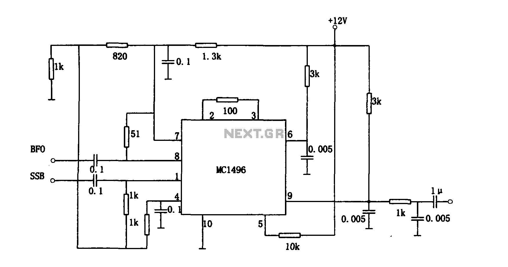
To recover the original modulating signal \( m(t) \) from a phase-modulated signal \( s(t) \), phase demodulation techniques utilize a reference signal whose phase can be manipulated. One widely used method is synchronous demodulation, often employed in conjunction with signal mixers or phase-locked loops (PLLs).
Synchronous Demodulation
Synchronous demodulation works by multiplying the received signal \( s(t) \) with a coherent reference signal \( \cos(2\pi f_c t + \phi_0) \), where \( \phi_0 \) is the phase of the reference signal. This operation effectively shifts the signal’s frequency spectrum and retains the original modulating signal, which can then be filtered to remove unwanted higher frequency components.
The multiplication yields:
Substituting \( s(t) \), we have:
Employing the trigonometric identity:
we simplify \( r(t) \) as follows:
Since the first cosine term oscillates at double the carrier frequency, only the second term remains relevant for demodulation:
By processing \( r(t) \) through a low-pass filter (LPF), we isolate the term related to the original signal \( m(t) \), allowing us to recover the modulating information.
Real-world Applications
Phase demodulation techniques find extensive application in digital communication systems, particularly in systems utilizing phase-shift keying (PSK). It is pivotal in ensuring robust signal recovery in noisy environments, thereby enhancing the reliability of data transmission. Additionally, these methods are integral to satellite communications, wireless networks, and various types of telemetry systems.
Conclusion
Phase demodulation plays a crucial role in coherent communication systems, allowing the extraction of information encoded in the phase of a carrier wave. This technique not only exemplifies the mathematical beauty of signal processing but also highlights its practical significance in various technological applications. A thorough understanding of phase demodulation equips engineers and researchers with the tools needed to innovate and improve modern communication systems.
3. Envelope Detection
Demodulation Techniques
3.1 Envelope Detection
In the realm of analog communication, envelope detection serves as a fundamental technique for demodulating amplitude-modulated (AM) signals. As an essential demodulation method, envelope detection capitalizes on the intrinsic variations in signal amplitude that directly correspond to transmitted data. This technique's effectiveness and simplicity allow it to remain a popular choice in various real-world applications, including radio broadcasting and audio transmission systems.
The core concept of envelope detection involves extracting the "envelope" of the received modulated waveform. This envelope is defined as the smooth curve that outlines the extremes of the oscillating signal. To visualize this, imagine a sine wave modulated by a lower frequency signal—envelope detection effectively utilizes a rectifier followed by a low-pass filter to retrieve the original message signal from the modulated carrier.
1. Theoretical Framework
Mathematically, consider an AM signal expressed as:
where:
- s(t): The modulated signal.
- A: The amplitude of the carrier wave.
- m(t): The message signal, containing the information we wish to recover.
- f_c: The frequency of the carrier wave.
The first step in envelope detection involves passing the received signal through a rectifier circuit, which typically can be a diode. The rectification converts the negative portions of the signal into positive ones, leading to an output that resembles the absolute value of:
This output is then analyzed to evaluate the envelope's shape. The challenge lies in isolating the signal m(t) from the resulting rectified waveform, which contains a high-frequency component due to the carrier wave.
2. Implementation Using Filters
After rectification, the next pivotal step is to employ a low-pass filter (LPF) that effectively attenuates high-frequency oscillations, thereby allowing only the lower frequency components (the message signal) to pass through. The cutoff frequency of the LPF should be set just above the highest frequency present in the message signal, ensuring a clean extraction of m(t).
The final form can be expressed as:
where H is the low-pass filtering operation performed on the rectified signal. Through this process, the original message transmission is successfully demodulated from the carrier wave.
3. Practical Considerations and Applications
In practice, envelope detectors are widely utilized due to their simplicity and effectiveness. Common applications include:
- Standard AM Radio: Most conventional AM radio receivers rely on envelope detection to extract audio from radio waves.
- Television Broadcasts: Envelope detection plays a crucial role in older television systems, particularly in the reception of analog signals.
- Acoustic Modems: These devices employ envelope detection to facilitate data communication over telephone lines by modulating digital signals onto an audio frequency carrier.
While envelope detection is efficient, it has limitations—such as susceptibility to distortion under conditions of low signal amplitude or strong noise interference. Nevertheless, it remains a key demodulation approach with significant applications in current technology.
In conclusion, mastering envelope detection enhances one's understanding of signal processing fundamentals while paving the way for more advanced demodulation techniques. Understanding the concepts behind this technique is crucial for engineers and researchers venturing deeper into the field of communications and signal processing.
3.2 Synchronous Detection
Synchronous detection is a prevalent demodulation technique primarily utilized in the recovery of amplitude-modulated (AM) signals. This method capitalizes on the importance of phase coherence between the carrier signal and the modulated signal, allowing for increased detection accuracy and reduced noise interference.
At its core, synchronous detection involves multiplying the incoming modulated signal by a locally generated carrier signal that is synchronized in both frequency and phase. This operation is crucial as it effectively demodulates the information encoded in the amplitude of the carrier wave while rejecting unwanted noise, leading to enhanced signal integrity.
The Principles of Operation
To understand how synchronous detection operates, we can represent the received modulated signal mathematically. Assume the modulated signal is represented as:
where:
- A(t) is the instantaneous amplitude carrying the information signal.
- fc is the carrier frequency.
- φ is the phase shift introduced during transmission.
In synchronous detection, the first step is to multiply this signal by a locally generated carrier wave of the same frequency and phase. This can be expressed as:
Expanding this, we can use the trigonometric identity:
Applying this identity gives:
The output simplifies to:
The first term represents a high-frequency component which can be filtered out, while the second term yields the baseband signal:
This baseband signal is effectively the original modulation signal, scaled by a constant factor. Through this multiplication, synchronous detection reclaims the amplitude information while minimizing interference from noise and other unwanted signals.
Real-World Applications
One of the primary applications of synchronous detection is in radio receivers, where AM signals transmitted over the air are demodulated. With the advent of digital signal processing, this technique has also been extended to digital communications, enabling effective methods for demodulating phase-shift keyed (PSK) signals.
The practical implications of synchronous detection extend beyond traditional radio systems; they are found in modern telecommunication systems, satellite communications, and even in radar systems, where precision and reliability in signal recovery are paramount. Implementing efficient synchronous detection algorithms can lead to significant improvements in data integrity and communication efficiency.
As researchers and engineers continue to explore advancements in demodulation techniques, the robust framework of synchronous detection remains a cornerstone in the field of signal processing, demonstrating its relevance and adaptability to new technological changes.
Demodulation Techniques
3.3 Application Examples
In the domain of communications, demodulation techniques serve pivotal roles across various applications, ranging from traditional radio broadcasting to modern digital data transmission. This section explores some significant application examples, highlighting how different demodulation strategies are employed to achieve efficient and effective data recovery.3.3.1 Amplitude Modulation (AM) Demodulation
Amplitude modulation (AM) is primarily used in analog audio broadcasting. In the early 20th century, the AM signal was the dominant form of radio transmission. The essential theory behind AM demodulation revolves around the detection of the varying amplitude of a carrier wave, which corresponds to the original audio information. One common method for demodulating AM signals is the envelope detector. The envelope is formed by the peaks of the modulated signal, and a simple diode followed by a low-pass filter extracts this envelope, which is then amplified. The mathematical representation of an AM signal can be expressed as:3.3.2 Frequency Modulation (FM) Demodulation
Frequency modulation (FM) offers improved sound quality and noise immunity compared to AM, making it preferable for music and voice transmission. FM demodulation employs several techniques, with the phase-locked loop (PLL) being one of the most effective. In a PLL, the FM signal is compared with a generated signal at the carrier frequency. The phase difference is then used to adjust the frequency of the generated oscillator, effectively locking onto the incoming signal's frequency variations. Mathematically, the instantaneous frequency of an FM signal can be described as:3.3.3 Digital Modulation Techniques
With the advancement of digital communications, various digital modulation techniques such as Phase Shift Keying (PSK) and Quadrature Amplitude Modulation (QAM) have gained prominence. These techniques require sophisticated demodulation methods to accurately retrieve the transmitted data. For instance, in PSK, the phase of the carrier signal is varied according to the input data. Demodulating PSK involves the use of the Costas loop, which synchronizes the demodulated signal's phase. The mathematical description for a binary PSK signal can be articulated as:4. Discriminator Techniques
4.1 Discriminator Techniques
In the realm of demodulation, discriminator techniques play a crucial role in recovering information from modulated signals. These techniques, which are particularly effective for frequency modulation (FM) signals, utilize the properties of adaptive signal processing to extract the original message signal after it has been altered by modulation.
Understanding Discrimination in Signal Processing
At their core, discriminator techniques operate by taking advantage of the relationship between frequency shifts and the amplitude of the modulated signal. When a signal is frequency-modulated, the instantaneous frequency of the carrier wave varies, resulting in a phase shift that can be traced back to the modulating signal. The task of a discriminator is to encode this phase information back into a form that can be interpreted as the original signal.
Types of Discriminator Techniques
Discriminator techniques can mainly be categorized into two types: Phase-Locked Loops (PLLs) and Zero-Crossing Detectors. Each method has its advantages and applicability, depending on the specific signal conditions and requirements.
Phase-Locked Loop (PLL) Discrimination
PLLs are integral components in numerous electronics applications, notably in communication systems for demodulating frequency-modulated signals. A PLL works by locking the phase of an oscillator to that of the incoming signal.
Key functional elements of a typical PLL include:
- Phase Detector: Compares the phase of the input signal to that of the oscillator, generating an output proportional to the phase difference.
- Low-Pass Filter: Smoothens the output of the phase detector to provide a steady control voltage to the voltage-controlled oscillator (VCO).
- Voltage-Controlled Oscillator (VCO): Adjusts its frequency based on the control voltage fed from the filter.
The primary advantage of PLL-based discrimination is its robustness against noise and its capability to produce high-fidelity outputs, making it suitable for applications such as broadcast FM radio and digital data communications. As the input frequency deviates, the phase detector generates a corresponding error signal to guide the VCO, hence realigning the received frequency to match the original oscillation.
Zero-Crossing Detector
Another straightforward and effective method for frequency demodulation is the use of a zero-crossing detector. This technique counts the number of times the signal crosses the zero voltage level within a certain time frame, thereby inferring the frequency modulation.
Here's how it operates:
- The input signal is monitored for instances when it crosses zero.
- The frequency is determined based on the rate of these crossings over a defined time interval.
- A comparison is made between the crossing rate and a reference frequency, allowing for the demodulation of the signal.
Zero-crossing detectors are widely used in applications where simplicity and low cost are paramount, such as in basic radio receivers and data acquisition systems.
Practical Applications of Discriminator Techniques
Discriminator techniques are utilized in a variety of fields and applications. These include:
- Radio Frequency Communications: Used extensively in FM radio reception to demodulate audio signals.
- Television Transmission: Essential in delivering audio and visual content through FM-modulated signals.
- Satellite Communications: Critical in the recovery of data from modulated signals transmitted over long distances.
These diverse applications illustrate the significance of understanding discrimination techniques in modern communication technology, especially as we continue to enhance and innovate within the field.
Conclusion
In summary, discriminator techniques serve as fundamental tools in the demodulation of frequency-modulated signals, effectively translating frequency shifts back into information. The combination of PLL and zero-crossing detector methods provides engineers and researchers multiple approaches to achieve accurate demodulation in varied practical scenarios.
4.2 Phase-Locked Loop (PLL)
The Phase-Locked Loop (PLL) is a fundamental technique in demodulation processes primarily used for synchronizing the phase of a local oscillator with the phase of a received signal. PLLs have found extensive applications in various domains, such as telecommunications, frequency synthesis, and data recovery. The ability of a PLL to track and maintain coherence with an input signal makes it an invaluable tool in the arsenal of electronic engineers and physicists alike.The Basic Principle of PLL
At its core, a PLL compares the phase of a reference signal with the phase of an output signal generated by a Voltage-Controlled Oscillator (VCO). The goal is to align the output frequency and phase with that of the input reference signal. The primary components of a PLL include:- Phase Detector (PD): This component produces an output that is proportional to the phase difference between the input signal and the VCO output.
- Low-Pass Filter (LPF): This filters the output of the phase detector to eliminate high-frequency components, providing a smooth control signal to the VCO.
- Voltage-Controlled Oscillator (VCO): The VCO generates a periodic output signal whose frequency is controlled by the voltage input from the low-pass filter.
Mathematical Representation
To quantitatively understand PLL performance, we derive a simple model of its operation. Assume \( V_{out} \) is the output voltage from the low-pass filter, which directly influences the frequency of the VCO. The phase difference \( \phi \) between the input signal \( V_{in} \) and the VCO output \( V_{VCO} \) can be expressed as:Applications of PLL
PLLs have a wide array of practical applications. Their most common uses include:- Frequency Synthesis: PLLs are employed to generate precise frequencies for clock signals in microprocessors and communication systems.
- Demodulation of FM signals: In FM radio receivers, PLLs are ideal for extracting information from frequency-modulated carriers.
- Clock Recovery: In digital communications, PLLs recover clock signals from incoming data streams, ensuring synchronization.
Historical Context and Innovations
The first PLLs were developed in the 1930s, initially used in radar systems. However, it wasn’t until the 1960s and 1970s that advanced PLL designs evolved, leading to their integration into modern digital systems. Innovations such as the Digital Phase-Locked Loop (DPLL) further enhanced the versatility of PLLs, showcasing their importance in contemporary applications. As digital communication requirements increase, PLL technology continues to adapt and remain relevant. In summary, the Phase-Locked Loop is a powerful and versatile tool in electronics, crucial for maintaining signal integrity and synchronizing system components. Its ability to adapt and function in real-time solidifies its role in advanced electronic systems, making it a pivotal concept in modern telecommunications and signal processing fields.4.3 Application Examples
Demodulation techniques are crucial for extracting usable information from modulated signals. Variations in modulation methods address diverse challenges across various communication applications. Here, we will explore several application examples that highlight different demodulation techniques in real-world scenarios.
Subsection: Wireless Communications
In wireless communication, one of the most prevalent applications is in cellular networks, where amplitude modulation (AM) and frequency modulation (FM) techniques are utilized for voice and data transmissions. For instance, the demodulation of FM signals can be efficiently achieved using a phase-locked loop (PLL). This technique leverages the PLL's ability to track the phase of incoming signals and adjust the output frequency accordingly, which is vital for maintaining signal integrity in cellular networks.
Here, \( f_{\text{out}} \) represents the output frequency, \( f_{\text{ref}} \) is the reference frequency, \( K_{\text{PL}} \) is the phase-locked loop gain, and \( V_{\text{in}} \) and \( V_{\text{offset}} \) are the input voltage and offset, respectively. The performance of the PLL in demodulation increases the clarity and fidelity of voice transmissions, ensuring better user experiences in mobile applications.
Subsection: Television Broadcasting
Television broadcasting employs analog and digital modulation techniques. Analog TV uses amplitude modulation (AM) for video signals and frequency modulation (FM) for audio signals. In contrast, digital television relies on advanced techniques such as quadrature amplitude modulation (QAM). Demodulation in QAM involves separating out two amplitude-modulated signals that are out of phase by 90 degrees.
Demodulating QAM signals can be achieved through a method called symbol decoding, which interprets how a signal’s phase and amplitude represent data. This approach is essential to recover high-definition video signals efficiently.
Mathematical Approach to QAM Demodulation
Let’s consider a QAM signal defined as:
Where \( S \) is the transmitted signal, \( I(t) \) is the in-phase component, \( Q(t) \) is the quadrature component, and \( f_c \) is the carrier frequency. To demodulate this signal, we multiply it by the carrier signals for both cosine and sine and then pass through a low-pass filter to recover \( I(t) \) and \( Q(t) \). From these components, the original signal can be reconstructed.
Subsection: Data Communication Systems
Data communication systems utilize various modulation schemes, including phase-shift keying (PSK), particularly in scenarios such as satellite communication and digital data transmission over optical fibers. A typical example is the use of Costas loops for demodulating PSK signals, which can effectively synchronize and demodulate the carrier signal without prior knowledge of its phase.
The Costas loop's architecture allows for the recovery of both the frequency and phase of the incoming signal. The loop consists of mixers, low-pass filters, and feedback components to provide real-time phase adjustments, which are critical for ensuring data integrity through noisy environments encountered in satellite links.
Costas Loop Framework
Consider a PSK signal that can be described as:
Where \( A \) is the amplitude, \( f_c \) is the carrier frequency, and \( \phi \) is the phase. The Costas loop demodulates \( S(t) \) by continuously adjusting \( \phi \) until the output signal aligns with the original data pattern.
As we observe, demodulation techniques have diverse applications that are critical in enhancing communication systems. Their evolution continues to impact the reliability and effectiveness of modern telecommunications as technology advances.
5. Costas Loop
5.1 Costas Loop
In the landscape of communication systems, demodulation plays a pivotal role in extracting information from modulated signals. Among various demodulation techniques, the Costas loop stands out for its robust capability to synchronize the phase of carrier waves, specifically in phase-modulated signals. Developed by Robert Costas in the 1950s, this technique has foundational importance in indirect demodulation methods and is extensively utilized in applications ranging from digital communications to radar signal processing.Overview of the Costas Loop
The Costas loop serves as a phase-locked loop (PLL) specifically optimized for demodulating coherent signals. The key function of the Costas loop is to synchronize the phase of the received signal with that of a local oscillator. By using a feedback mechanism, it adjusts the oscillator's phase until it matches that of the incoming signal, ensuring that the demodulation process is accurate and efficient. At its core, the Costas loop can be understood as comprising three main components: a phase detector, a loop filter, and a voltage-controlled oscillator (VCO). The phase detector compares the phases of the incoming signal and the VCO output, yielding an error signal that the filter processes before feeding it back to the VCO for adjustment.Mathematical Formulation
To comprehend the functioning of the Costas loop mathematically, consider a received signal expressed as: $$ s(t) = A \cos(2\pi f_c t + 2\phi) $$ where: - \( A \) is the amplitude, - \( f_c \) is the carrier frequency, and - \( \phi \) is the phase shift introduced by the modulation process. The objective of the Costas loop is to adjust \( \phi \) to synchronize the VCO output with the incoming signal. Let's denote the VCO output by: $$ v(t) = K \cos(2\pi f_c t + \theta) $$ where: - \( K \) is the gain, and - \( \theta \) is the output phase of the VCO. The phase error \( e(t) \) can thus be defined as: $$ e(t) = \phi - \theta $$ Using a phase detector, we can derive the error signal which is typically proportional to the sine of the phase error: $$ E(t) = \sin(e(t)) = \sin(\phi - \theta) $$ After this, the loop filter processes \( E(t) \) to create a smooth control signal that adjusts the VCO phase, allowing it to converge on the desired synchronization. By employing a proportional-integral (PI) type of filter, we ensure stability and responsiveness in the approach to zero phase error.Practical Applications
The Costas loop is heavily employed in systems where accurate phase synchronization is required. Its applications extend to:- GPS Technology: Used for demodulating signals where accurate phase information is crucial for position determination.
- Digital Video Broadcasting (DVB): Essential in recovering the modulated bitstream in digital transmission standards.
- Software-Defined Radio (SDR): In SDR applications, Costas loops aid in demodulating complex modulated signals effectively.
Conclusion
In conclusion, the Costas loop is a sophisticated yet elegant solution to the challenges of phase demodulation. By maintaining continuous synchronization, it enhances the fidelity of signal reception in various practical contexts. Its foundational principles in phase-locked loop theory not only illustrate the intricate dance of control systems and signal processing but also pave the way for innovations in communication technologies. With the constantly evolving landscape of wireless communications, the Costas loop remains a cornerstone in the repertoire of demodulation techniques.5.2 Phase Discriminator
In communication systems, demodulation is a crucial step where the information signal is extracted from the modulated carrier wave. One prevalent method of demodulation is through the use of a phase discriminator. This technique particularly finds utility in phase modulation (PM) and frequency modulation (FM) systems, allowing engineers to decode the transmitted information effectively.Understanding Phase Discrimination
At its core, a phase discriminator is designed to measure the phase difference between two signals. It operates under the principle that any modulation — be it amplitude, frequency, or phase — can be interpreted by examining the variations in phase relationships. The output of a phase discriminator correlates directly with the phase shift of the input signal relative to a reference signal. This capability is particularly essential for demodulating signals in the presence of noise, which is ubiquitous in real-world environments.Types of Phase Discriminators
There are several architectures that can implement phase discrimination:- Balanced Modulator: This is a common form where the modulated signal is mixed with a local reference signal. The output produces components proportional to the phase difference.
- Phase Locked Loop (PLL): A PLL not only demodulates the signal but also performs synchronization tasks. It uses a feedback loop to maintain a constant phase relationship with the received signal.
- Zero-Crossing Detector: This simple variant detects the instants when the modulated signal crosses zero, allowing for an inference regarding its phase relative to a reference.
Mathematical Foundation
To establish a mathematical framework for understanding phase discriminators, consider two sinusoidal signals: the input signal \( V_{in}(t) \) given by: $$ V_{in}(t) = A \cos(\omega t + \phi) $$ and the reference signal \( V_{ref}(t) \): $$ V_{ref}(t) = A \cos(\omega t) $$ where: - \( A \) is the amplitude, - \( \omega \) is the angular frequency, - \( \phi \) is the phase shift introduced by the modulated signal. The phase discriminator’s output can be expressed as a function of the phase difference \( \phi \). Using trigonometric identities, we can compute the correlation between these two signals over one cycle. The output voltage \( V_{out} \) can be approximated as: $$ V_{out} \propto \sin\left(\phi\right) $$ This allows us to derive the relationship between the output voltage and the fractional phase shift. Thus, a voltage output that produces a higher magnitude indicates greater phase shift, facilitating the effective extraction of the transmitted information.Applications and Practical Relevance
In practice, phase discriminators find application in several critical areas:- Telecommunications: Used in demodulating FM signals in radio stations and mobile communications.
- Navigation Systems: Integral to GPS technology where accurate phase measurements help in calculating position and timing.
- Data Recovery: Utilized in digital communication systems to extract data signals from phase-shift keying schemes.
5.3 Application Examples
In exploring demodulation techniques, it is vital to contextualize these methods within practical applications that showcase their significance. Demodulation serves as a bridge between modulated signals—those altered to transmit information over various mediums—and the original message or data. This section presents several examples illustrating the implementation and impact of different demodulation techniques in real-world scenarios.Demodulation in Communication Systems
One of the most prominent applications of demodulation is in communication systems, where it plays a critical role in the recovery of transmitted information. For instance, in amplitude modulation (AM) broadcasting, the demodulation process involves extracting the audio signal from the modulated carrier wave received by a radio. The demodulation of AM signals often employs a simple envelope detector, which consists of a diode and a low-pass filter. The diode rectifies the incoming signal, while the filter smoothens it to retrieve the original audio waveform. This technique is not only prevalent in commercial radio broadcasting but also in two-way radio communications, such as those used by emergency services. The reliability and simplicity of AM demodulation techniques ensure that clear communication can be maintained in critical situations.Demodulation in Wireless Technology
With the advent of digital communication systems, the application of demodulation techniques has broadened. For example, in wireless networks, Frequency Shift Keying (FSK) and Phase Shift Keying (PSK) are commonly used to transmit data. Demodulators for these types employ coherent detection methods where the phase of the received signal is compared against a reference signal to accurately reconstruct the transmitted data. One key application is in mobile phone technology, where PSK has been adopted in various standards, including GSM and CDMA. The demodulation process enhances data integrity, allowing users to maintain stable and secure communications even in environments with significant interference, such as urban areas.Demodulation in Satellite Systems and GPS
Another critical field is satellite communication, where demodulation is crucial for decoding the signals transmitted from satellites to ground stations. This process is essential for systems like GPS. In GPS technology, signals are transmitted using Binary Phase Shift Keying (BPSK). The demodulation is performed using sophisticated algorithms that account for signal propagation delays, Doppler shifts, and other atmospheric conditions. The ability to accurately demodulate these signals allows GPS receivers to calculate precise locations, which is vital for navigation applications. Furthermore, such techniques are increasingly being utilized in various sectors, including precision agriculture and autonomous vehicle navigation systems, emphasizing the practical implications of this technology.Emerging Applications in Software-Defined Radio (SDR)
As technology advances, software-defined radio (SDR) has emerged as a flexible platform for implementing a multitude of demodulation techniques. SDR utilizes software to perform signal processing tasks traditionally handled by hardware, allowing for adaptability to various modulation schemes and standards. For instance, engineers can design SDR systems capable of switching between modulation types on the fly, significantly enhancing the efficiency of communication in dynamic environments. Applications range from emergency communications to commercial aviation, where SDR enables robust, multi-channel communications systems tailored to specific operational needs. Integrating advanced demodulation techniques into SDR showcases the transformative potential of combining software innovation with radio technology, presenting exciting possibilities for future communications systems.Summary
The examples provided illustrate how demodulation techniques are vital across various domains, from traditional broadcasting to advanced digital communication systems. As engineers and researchers further explore these applications, the continued evolution of demodulation methods stands to revolutionize how we communicate, navigate, and connect in our increasingly digital world. In conclusion, the significance of demodulation transcends pure theory; its practical application underpins systems we rely on daily, paving the way for future innovations in technology.6. Advantages and Disadvantages
6.1 Advantages and Disadvantages
Demodulation is an essential process in communication systems, allowing for the extraction of information from modulated carrier signals. Various demodulation techniques exist, each bringing its own set of advantages and disadvantages. Understanding these trade-offs is critical for engineers and researchers who aim to optimize communication systems for specific applications.
Advantages of Demodulation Techniques
Demodulation techniques offer several advantages, depending on their design and application:
- Simplicity: Techniques such as envelope detection are straightforward to implement, requiring minimal complexity in both hardware and software.
- Cost-Effectiveness: Lower complexity often leads to reduced costs; simpler demodulation schemes can be cheaper to manufacture and deploy.
- Low Power Consumption: Less complex demodulators typically consume less power, making them suitable for battery-operated devices.
- Robustness Against Noise: Certain demodulation techniques, such as phase-locked loops (PLLs), enhance system resilience against noise and interference, improving signal quality.
- Versatility: Many demodulation techniques can be adapted to various types of modulation schemes, allowing for a wide range of applications.
Disadvantages of Demodulation Techniques
Despite their advantages, demodulation techniques are not without limitations:
- Complexity and Performance Trade-offs: More complex techniques often yield better performance and higher data rates but are also more expensive and power-hungry.
- Vulnerability to Signal Distortion: Some demodulation techniques are sensitive to distortion caused by multipath propagation in wireless channels, which can lead to data loss.
- Limited Range of Operation: Techniques designed for specific modulation methods may not perform well when applied to others, limiting their generalizability.
- Calibration and Configuration: More advanced techniques can require significant calibration and setup, increasing deployment time and potential for error.
Practical Relevance
The choice of demodulation technique can have far-reaching implications in real-world applications. For instance, in mobile communications, where devices often operate under varying conditions, selecting a robust demodulation method can enhance user experience by reducing call drops and improving data speeds. Similarly, in satellite communications, techniques that can effectively mitigate noise are paramount for ensuring signal integrity over long distances.
As communications technology evolves, engineers and researchers must consider not just the advantages but also the inherent disadvantages of these techniques when designing their systems. An informed choice based on the specific requirements of a given application can lead to significant improvements in performance, cost efficiency, and user satisfaction.
6.2 Criteria for Selecting a Demodulation Technique
The selection of an appropriate demodulation technique is critical for the successful recovery of transmitted information from a modulated signal. Various factors influence this choice, and the engineer must consider these criteria within the context of the specific application. Here, we delve into essential criteria that should guide the decision-making process, ensuring optimal performance and reliability.
Performance Requirements
Different demodulation techniques exhibit various performance characteristics under different conditions. When evaluating performance, consider:
- Signal-to-Noise Ratio (SNR): Techniques may operate effectively at varying SNR levels. For instance, Phase Shift Keying (PSK) can offer superior performance compared to Amplitude Shift Keying (ASK) in noisy environments.
- Bit Error Rate (BER): Assessing the expected BER is essential. Techniques that can maintain low BER under high noise or fading conditions are often preferable for critical communications.
- Bandwidth Efficiency: This factor measures how effectively a modulation scheme utilizes the available bandwidth. Quadrature Amplitude Modulation (QAM) is known for its ability to transmit more bits per symbol than simpler schemes, which could be advantageous in bandwidth-limited scenarios.
Complexity and Implementation Feasibility
The complexity of the demodulation algorithm impacts the feasibility of its implementation in various hardware platforms:
- Algorithmic Complexity: Simpler algorithms are easier to implement and may require less processing power, making them more suitable for embedded systems with limited resources.
- Hardware Availability: Some demodulation techniques may demand specialized hardware (e.g., Digital Signal Processors (DSPs)) for real-time processing, which could constrain their use in budget-sensitive applications.
Application Context
The intended use of the communication system can greatly influence the choice of demodulation technique:
- Type of Service: Voice, video, or data transmission may require different robustness and latency requirements, influencing the choice of modulation scheme.
- Mobility Conditions: Applications that involve moving transmitters or receivers, such as mobile phones, often require robust demodulation techniques that can handle multipath fading.
Environmental Factors
Operational environments vary widely, and considerations must include:
- Interference: The level of interference present can dictate the robustness of the selected demodulation technique. Some techniques, such as Orthogonal Frequency Division Multiplexing (OFDM), are designed specifically to mitigate interference effects.
- Propagation Conditions: In rural versus urban environments, fading, shadowing, and other distortion effects may require different demodulation strategies to maintain signal integrity.
Scalability and Adaptability
The final criteria involve the scalability of the demodulation technique:
- Scalability: Consider whether the technique can handle future expansions in data rate or additional users without requiring significant modifications.
- Adaptability: Techniques that can adapt to varying channel conditions (for instance, through automatic gain control or adaptive equalization) may be preferable for dynamic environments.
In summary, selecting the appropriate demodulation technique encompasses a multi-faceted assessment. Understanding the intersection of performance requirements, implementation feasibility, application context, environmental factors, and scalability ensures the effective recovery of information in a real-world setting. Continuing advancements in technology will likely expand the toolkit of available demodulation techniques, making this an exciting field for future exploration and innovation.
7. Radio Communications
7.1 Radio Communications
Demodulation techniques are essential in the realm of radio communications, allowing the transmission of information over distances by converting modulated signals back into their original form. This process is crucial in applications ranging from terrestrial radio broadcasting and satellite communications to cellular networks. Understanding the different demodulation techniques and their principles can equip engineers, physicists, and researchers with the necessary tools to design and optimize communication systems.
Fundamentals of Modulation and Demodulation
Before delving into specific demodulation techniques, it is vital to understand the modulation process itself. Modulation is the method of varying a carrier signal's properties—such as amplitude, frequency, or phase—to encode the information signal. The three primary types of modulation include:
- Amplitude Modulation (AM) — where the amplitude of the carrier signal changes in accordance with the information signal.
- Frequency Modulation (FM) — where the frequency of the carrier signal varies based on the information signal.
- Phase Modulation (PM) — where the phase of the carrier signal is altered to encode information.
Demodulation, conversely, is the reverse process, whereby the encoded information is extracted from the modulated carrier wave. This section focuses on various demodulation techniques used in radio communications.
Envelope Detection for AM Signals
For amplitude modulated signals, envelope detection is one of the simplest and most common demodulation techniques. The envelope of the AM signal represents variations in amplitude that correspond to the original information signal.
The basic envelope detector consists of a diode, which rectifies the incoming signal, followed by a low-pass filter to smooth out the signal and recover the information. The diode allows current to flow in only one direction, thus producing an output proportional to the envelope of the input signal. The mathematical representation of this process can be summarized as follows:
Here, \( V_{in}(t) \) is the input AM signal, and \( T \) is the time period of interest. The output voltage is filtered to produce a smooth representation of the original signal.
Phase-Locked Loop (PLL) for FM Signals
As frequency modulation (FM) conveys information in the form of variations in frequency, the phase-locked loop (PLL) is a robust demodulation technique utilized widely in FM applications. A PLL tracks the frequency of the received signal and adjusts its output to match that frequency, effectively demodulating the incoming FM signal.
A typical PLL structure consists of a phase detector, low-pass filter, and voltage-controlled oscillator (VCO). The operation can be described in the following steps:
- The phase detector compares the phase of the incoming signal with that of the VCO output.
- The resulting phase difference controls the VCO to adjust its frequency accordingly.
- The output of the VCO ultimately corresponds to the demodulated signal.
Mathematically, the relationship maintained in a PLL can be represented as follows:
Here, \( K \) denotes the gain factor that defines how aggressively the PLL responds to phase discrepancies. This feedback loop is crucial in maintaining synchronization and ensuring the effective extraction of the desired information from the FM signal.
Quadrature Amplitude Modulation (QAM) and Its Demodulation
Quadrature Amplitude Modulation (QAM) is a versatile modulation technique combining both amplitude and phase modulation. It is widely used in digital radio communications due to its capacity to transmit a higher amount of data within the same bandwidth. QAM signals can be demodulated using coherent detection methods, which require precise synchronization with the carrier signal's phase.
The process involves mapping the received signals to predefined symbols in a constellation diagram. Each point on the diagram represents a unique combination of amplitude and phase. The mathematical representation of a QAM signal may be expressed as:
Where \( I(t) \) and \( Q(t) \) represent the in-phase and quadrature components respectively. The demodulation process typically employs a matched filter, followed by a decision-making algorithm to determine the closest point in the constellation diagram, thus recovering the original data.
Demodulation techniques, such as those covered above for AM, FM, and QAM, are at the heart of modern radio communication systems. Their implementations not only hinge on theoretical principles but also require rigorous optimization to withstand real-world conditions including noise and interference.
As radio communications continue to evolve with advancements in technology, understanding these demodulation methods will remain critical for engineers and researchers working to improve data integrity and transmission efficiency.
7.2 Data Transmission
Data transmission is a crucial element in communication systems, encompassing the methods by which information is conveyed from one point to another. In the context of demodulation techniques, it becomes vital to understand how these processes affect the integrity and efficiency of signal transmission. This section delves into data transmission methodologies, focusing particularly on their relevance in a demodulation framework.
Understanding the Concept of Data Transmission
Data transmission typically involves encoding information into a signal that can be efficiently transferred over various media, such as air or cables. The common types of data transmission include:
- Analog Transmission: This involves sending information in the form of continuous signals, which can represent various states (e.g., sound waves).
- Digital Transmission: In digital communication, data is encoded into binary format (0s and 1s), which offers greater resistance to noise and interference.
- Serial Transmission: Data is transferred one bit at a time over a single channel, often used in long-distance communications.
- Parallel Transmission: Multiple bits can be sent simultaneously across multiple channels, allowing for faster communication over short distances.
The choice of transmission method can significantly impact the performance and reliability of the communication link, influencing factors such as bandwidth, latency, and error rates.
Modulation and Demodulation in Data Transmission
Based on the chosen transmission method, modulation techniques are applied to encode the signal. Common modulation techniques include:
- Amplitude Modulation (AM): Varies the signal's amplitude to represent data.
- Frequency Modulation (FM): Changes the frequency of the signal to encode data.
- Phase Modulation (PM): Adjusts the phase of the signal wave to signify different data points.
After transmission, the receiver must demodulate the signal to retrieve the transmitted data accurately. Effective demodulation is essential because any distortions introduced during the transmission can lead to data corruption.
Animal Analogies: An Insightful Approach
Daily life often provides real-world analogies for these concepts. For instance, consider a scenario in nature where a bird (the transmitter) sings a melody (the modulated signal) over a distance to communicate with another bird (the receiver). If the melody is distorted by wind (interference), the receiving bird may misinterpret the message. Similarly, in data transmission, maintaining the clarity of the transmitted signal is essential for proper interpretation.
Key Challenges in Data Transmission
Data transmission faces a variety of challenges, including:
- Interference: Noise from external sources can disrupt the signal.
- Bandwidth Limitations: Available frequency ranges can limit the amount of data transmitted.
- Latency: Delays in data transfer can affect real-time applications.
- Signal Attenuation: Loss of strength in a signal over distance can lead to errors in data interpretation.
Mathematical Representation of Data Transmission Performance
To quantitatively analyze data transmission performance, the Bit Error Rate (BER) is often employed. BER represents the ratio of incorrect bits to the total number of bits transmitted, and it can be mathematically expressed as follows:
Where:
- Ne: Number of erroneous bits
- Nt: Total number of transmitted bits
A lower BER indicates a more reliable transmission method, which is crucial in applications such as satellite communication, data networking, and broadcasting.
Real-World Application: The Internet of Things (IoT)
In the context of modern technology, the Internet of Things (IoT) exemplifies the practical implications of advanced data transmission techniques. Devices interconnected through wireless communication protocols rely on efficient data transfer mechanisms and robust demodulation techniques. Evidence suggests that addressing the challenges associated with data transmission can significantly improve the performance of IoT systems, making them more efficient and reliable.
Ultimately, mastering data transmission techniques provides the foundation for improving the efficiency and effectiveness of various technologies, particularly in telecommunications and network design.
7.3 Satellite Communications
Satellite communications represent a crucial domain in modern telecommunications, enabling global connectivity for various applications, from broadcasting television signals to facilitating internet access in remote locations. At the heart of satellite communication is the challenge of effectively demodulating signals transmitted through vast distances in space, often subject to unique disturbances not typically encountered in terrestrial communications.
Fundamentals of Satellite Communication
The fundamental components of a satellite communication system include the transmitter, the satellite itself, and the receiver. The transmitter sends the modulated signal to the satellite, which amplifies and retransmits it back to Earth. The modulation used in these systems can vary based on bandwidth requirements and signal integrity concerns, with techniques like QPSK (Quadrature Phase Shift Keying) and 8PSK (8 Phase Shift Keying) being common owing to their spectral efficiency.
Demodulation in Satellite Communications
Demodulation serves as a pivotal step in recovering the original message from the modulated carrier wave. Understanding the various techniques employed in this process is essential for engineers and researchers involved in improving satellite communication technologies.
One of the primary challenges in satellite communication is dealing with the propagation delays and signal degradation caused by factors such as atmospheric conditions and Doppler shifts resulting from the satellite's movement. To counter these issues, advanced demodulation techniques must be employed.
1. Coherent Demodulation
Coherent demodulation involves synchronizing the local oscillator with the incoming signal's phase and frequency. It is essential for achieving optimal performance in systems using phase-modulated signals. The key equation governing coherent demodulation can be expressed as:
Here, \(y(t)\) represents the received signal, \(A\) is the amplitude, \(f_c\) is the carrier frequency, and \(\phi\) is the phase shift introduced during transmission. Properly aligning the local oscillator with \(y(t)\) allows accurate extraction of the modulated information.
2. Non-Coherent Demodulation
In non-coherent demodulation, the amplitude and phase of the carrier wave are not explicitly tracked. Instead, this technique focuses on the signal envelope or energy detection, which simplifies processing requirements, making it ideal for environments with high noise levels. Common non-coherent techniques include:
- Envelope Detection: Utilizing an envelope detector circuit to retrieve the modulated information directly from the amplitude variations.
- Energy Detection: Measuring the energy levels of received signals to determine their characteristics without precise phase information.
3. Adaptive Demodulation
Adaptive demodulation techniques dynamically adjust parameters based on real-time channel conditions, offering improved performance under varying frequency conditions, such as those presented by the Van Allen radiation belts and terrestrial interference. This adaptability is crucial for maximizing throughput and maintaining link quality.
Practical Applications and Future Directions
Real-world implementations of demodulation techniques in satellite communications can be found in applications like global broadcasting services, earth observation systems, and the expanding realm of internet satellites. Continuous advancements in signal processing algorithms, coupled with improved hardware such as Software-Defined Radios (SDRs), promise to enhance the efficiency and reliability of satellite communications in the coming years.
As technologies evolve, especially with the emergence of Low Earth Orbit (LEO) satellite constellations, innovative demodulation strategies will play a crucial role in managing increased data rates and complex interference patterns. Understanding these techniques not only prepares professionals for current challenges but also equips them to innovate solutions for future communication paradigms.
8. Suggested Textbooks
8.1 Suggested Textbooks
- Electronic Communications Systems by Wayne Tomasi — This book provides comprehensive coverage of communication systems, delving into both analog and digital methods. Known for its clarity, it covers demodulation techniques in the context of broader communication theory.
- Communication Systems Engineering by John G. Proakis and Masoud Salehi — Featuring an in-depth analysis of different modulation schemes, this text provides engineers and mathematics professionals with detailed derivations and explanations suited for advanced studies.
- Modern Digital and Analog Communication Systems by B.P. Lathi and Zhi Ding — This book blends traditional communication concepts with modern technologies and techniques, including the latest on digital communication and modulation/demodulation mechanisms.
- Fundamentals of Wireless Communication by David Tse and Pramod Viswanath — Focusing on the burgeoning field of wireless communication, this textbook expounds on advanced demodulation techniques critical for understanding current wireless technologies.
- Signals, Systems, and Communication by B.P. Lathi and Roger Green — Offering solid grounding in signal processing, this textbook covers systematic approaches to analyzing and understanding demodulation within the larger scope of communication systems.
- Communications Receivers: DSP, Software Radios, and Design by Ulrich L. Rohde, Jerry C. Whitaker, T.T.N. Bucher — This book provides real-world applications of receiver design, highlighting the role of advanced demodulation techniques in modern communication technologies.
- Communication Systems Engineering by Ajay Gnanavel — For those diving into practical engineering applications, this book elucidates communication theories alongside real-world strategies, particularly in advanced demodulation techniques.
8.2 Research Articles
- A Review of Demodulation Techniques — An insightful review of different contemporary demodulation techniques that include advantages and challenges, with deep dives into their theoretical backgrounds and application areas.
- Digital Demodulation Methods: A Comprehensive Survey — This paper presents an exhaustive survey of digital demodulation methods, identifying key techniques, potential applications, and future trends in telecommunication systems.
- Enhanced DSP Algorithms for Optical Signal Demodulation — The article discusses innovative DSP algorithms designed for optical signal demodulation, highlighting the improvements in processing speed and accuracy.
- Adaptive Demodulation Techniques for Real-time Communication Systems — Provides an in-depth exploration of adaptive demodulation techniques that are optimized for real-time communication applications, emphasizing reliability and efficiency.
- Machine Learning in Demodulation: Challenges and Opportunities — Investigates the role of machine learning in evolving demodulation techniques, discussing the opportunities and challenges that come with integrating AI algorithms.
- Efficient Demodulation Techniques for MIMO Systems — Describes the integration of advanced demodulation techniques into MIMO systems, highlighting improvements in data throughput and error reduction.
- Analysis of PLL-Based Demodulation Techniques — This article reviews Phase-Locked Loop (PLL) based demodulation techniques, noting their significance in ensuring signal integrity and performance in various communication environments.
- Advancements in Coherent Demodulation for Satellite Communication — Discusses advancements in coherent demodulation techniques specifically developed for satellite communication systems, emphasizing their role in enhancing signal processing capabilities.
8.3 Online Resources
- Analog Devices Webcasts — Offers a series of webcasts that delve into advanced topics like demodulation techniques and signal processing applications, bridging theoretical concepts with practical implementations.
- Electronics Tutorials - Angle Modulation — Provides a comprehensive tutorial on angle modulation including Phase and Frequency Modulation, useful for understanding various demodulation techniques.
- RP Photonics - Demodulation — This resource offers an in-depth look at demodulation with a focus on optical applications, beneficial for researchers in photonics.
- Coursera - Digital Signal Processing — An online course covering a wide range of digital signal processing topics, including demodulation techniques, taught by esteemed professors.
- University of Washington - ISDL Publications — Hosts a collection of research papers and technical documents focusing on advanced signal processing strategies, including new methods in demodulation.
- TeachEngineering - Introduction to Signal Processing — This lesson introduces the core principles of signal processing, providing background knowledge essential for mastering demodulation techniques.
- SpringerLink - Advanced Signal Processing Techniques — Offers access to research articles on cutting-edge digital and analog signal processing methods including contemporary demodulation practices.
- IEEE Xplore Digital Library — A vast repository of peer-reviewed papers and publications on various topics in electronics and communications, including detailed studies on demodulation techniques.