
Differential-instrumentation-amplifier
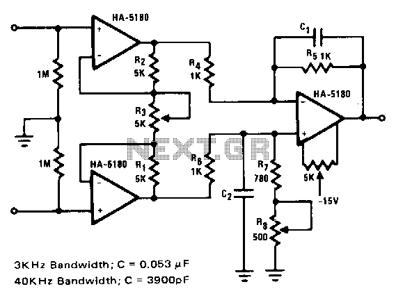
This circuit relies on extremely high input impedance for effective operation. The HA-5180 with its JFET input stage performs well as a preamplifier. The standard three-amplifier configuration is used with very close matching of the resistor ratios R5/R4 and (R7 + R8)/R6 to ensure high common-mode rejection (CMR). The gain is controlled through R3 and is equal to 2RI/R3. Additional gain can be achieved by increasing the ratios R5/R4 and (R7 + R8)/R6. The capacitors C1 and C2 improve the AC response by limiting the effects of transients and noise. Two suggested values are provided for maximum transient suppression at frequencies of interest. Some of the faster digital voltmeters (DVMs) operate at a peak sampling frequency of 3 kHz, hence the 4 kHz low-pass time constant. The 40 kHz low-pass time constant for AC voltage ranges is an arbitrary choice but should be selected to match the bandwidth of the other components in the system. C1 and C2, however, might reduce CMR for AC signals if not closely matched. Input impedances have also been added to provide adequate DC bias currents for the HA-5180 when open-circuited.
This circuit design emphasizes high input impedance, which is crucial for minimizing loading effects on the signal source, thereby ensuring accurate signal amplification. The HA-5180 operational amplifier, featuring a JFET input stage, is adept at functioning as a preamplifier, allowing it to handle low-level signals with minimal distortion. The configuration employs three amplifiers, strategically arranged to maximize performance through precise matching of resistor ratios. The close matching of the resistors R5/R4 and (R7 + R8)/R6 is essential for achieving a high common-mode rejection ratio (CMRR), which is vital in applications where noise rejection is necessary.
Gain control is achieved via resistor R3, with the gain formula outlined as 2RI/R3, where RI represents the input resistance. This configuration allows for flexibility in gain adjustment, with additional gain attainable by altering the resistor ratios. The capacitors C1 and C2 serve to enhance the AC response of the circuit by mitigating transients and noise. The selection of capacitor values is critical; two recommended values are indicated for optimal transient suppression, particularly for systems that may operate at higher frequencies.
In scenarios where digital voltmeters are utilized, especially those with peak sampling frequencies around 3 kHz, a low-pass time constant of 4 kHz is implemented to filter out high-frequency noise and transients. Additionally, a 40 kHz low-pass time constant is used for AC voltage ranges, which, while somewhat arbitrary, should align with the bandwidth requirements of associated components to maintain signal integrity.
It is important to note that while C1 and C2 enhance performance, they must be closely matched to avoid compromising CMR for AC signals. Furthermore, the inclusion of input impedances is a thoughtful design choice, ensuring that sufficient DC bias currents are provided to the HA-5180 when the circuit is in an open-circuit condition, which is vital for maintaining operational stability and accuracy.This circuit relies on extremely high input impedance for effective operation. The HA-5180 with its JFET input stage, performs well as a preamplifier. The standard three amplifier configuration is used with very close matching of the resistor ratios R5/R4 and (R7 + R8)/R6, to insure high common-mode rejection (CMR). The gain is controlled through R3 and is equal to 2RI/R3. Additional gain can be had by increasing the ratios R5!R4 and (R7 + R8)!R6. The capacitors C1 and C2 improve the ac response by limiting the effects of transients and noise. Two suggested values are given for maximum transient suppression at frequencies of interest. Some of the faster DVM"s are operating at peak sampling frequency of 3-kHz, hence the 4-kHz, low-pass time constant. The 40kHz, low-pass time constant for ac voltage ranges is an arbitrary choice, but should be chosen to match the bandwidth of the other components in the system.
C1 and C2 might however, reduce CMR for ac signals if not closely matched. Input impedances have also been added to provide adequate de bias currents for the HA-5180 when open-circuited. 🔗 External reference
Warning: include(partials/cookie-banner.php): Failed to open stream: Permission denied in /var/www/html/nextgr/view-circuit.php on line 713
Warning: include(): Failed opening 'partials/cookie-banner.php' for inclusion (include_path='.:/usr/share/php') in /var/www/html/nextgr/view-circuit.php on line 713