
Digital AC Voltmeter
The schematic design integrates several essential components to facilitate the operation of the digital voltmeter. The 555 timer, configured in astable mode, generates a stable sawtooth waveform that serves as the basis for the PWM signal generation. The comparator plays a crucial role by comparing this sawtooth waveform against the scaled analog DC voltage, producing a PWM signal whose duty cycle corresponds to the input voltage level.
The voltage divider circuit is vital for ensuring that the sawtooth waveform remains within the operational limits of the comparator. This scaling is necessary to prevent damage to the components and to ensure accurate readings. Adjusting the 10K resistor allows for fine-tuning of the sawtooth waveform characteristics, ensuring optimal performance.
The CD4518 counter chip is configured to handle the counting of pulses generated by the PWM signal. The design takes advantage of the dual decade counting capability, allowing for a straightforward representation of the voltage level on a 2.5-digit display. The integration of the flip-flop registers using the 74LS175 and CD4013 ensures that the output from the counter is latched correctly for display purposes.
In summary, this digital AC voltmeter design effectively utilizes a combination of analog and digital components to achieve accurate voltage measurements, providing a practical solution for monitoring AC voltages in various applications. The use of readily available components emphasizes the DIY aspect of the project while maintaining a focus on functionality and accuracy.It started out as a simple unenclosed variac (variable autotransformer) and electrical outlet mounted on a block of wood. I eventually put it in the case of what used to be an old audio signal generator for safety and appearance.
Among the other added features, I used a 0-250VAC analog meter that I had on hand to display the output voltage because otherwise it was annoying to whip out the multimeter to monitor the voltage coming out of the variac. Over the years I realized that the meter was inaccurate and simply useless, so a new readout was necessary. I wanted a digital AC voltmeter to measure the output range from 0 to 150VAC with reasonable accuracy.
Sure I could buy some premade DVM packages or use a microcontroller with a built-in ADC, but I wanted to make one from scratch myself using readily available parts I had on hand. I aimed for reasonable accuracy so I chose to have a 2 and a half display for the voltage, meaning the meter reads from 000 to 199.
Below is the schematic of the AC DVM: I used a voltage-controlled PWM circuit to convert an analog DC voltage to a pulse duty cycle. To do this, a 555 timer is used to generate a sawtooth wave at about 500Hz that is fed into a comparator to compare against the measured analog DC voltage.
The output of the comparator has 500Hz period with a pulse width that is proportional to the input DC voltage. However, the sawtooth swing is only around 1. 65 to 3. 3V so a voltage divider between 5V and the measured DC voltage is used to offset and scale down the swing to this range.
The 10K resistor on the sawtooth 555 timer is for adjusting the transistor bias to control the current going into the 0. 1uF capacitor. Adjust this until the sawtooth is as clean as possible and has the 1. 65-3. 3V range and the correct frequency. Be careful not to adjust the pot all the way to ground or you could blow the 2N3906 transistor. Adding 1K resistors around the pot would be safer but I used just the pot to reduce parts count. The circuitry in the upper half of the schematic could actually be used as a frequency counter. The CD4518 is a dual decade counter chip that is wired to count from 00 to 99. CPB~ to advance the B counter is negative-edge triggered so when the A counter transitions from 0111 to 1000, the fourth bit doesn`t trigger the B counter.
When the A counter rolls over from 1001 to 0000, the negative edge triggers B to advance once. The CD4013 flip-flop for the third digit advances on a positive edge clock, so a transistor inverter is used on the fourth bit from the B counter output so when it rolls over from 1001 to 0000, the transistor drives the CD4013 clock with a positive edge. The 74LS175 and second half of the CD4013 are used as flip-flop registers to grab the counter output for display on a rising edge of LOAD.
Also, when LOAD goes high the CD4518 will reset to clear its counts. To use the counter as a frequency counter, all one would need to do is feed 1Hz, 10Hz, etc. into LOAD to serve as the "gate. " When measuring 60Hz for instance, the counter will count from 000 to 060 in 1 second and then the gate enables LOAD to reset the count and the 74LS175`s grab 060 to display. The counter will again begin to count from 000 to 060 in the next second and so on. If the gate speed is raised to 10Hz then the counter only has 0. 1 seconds to count and will count from 000 to 006, and multiply this by 10 to get the frequency representation.
Essentially a 10Hz gate speed changes the frequency range from 000-199Hz to 0000 - 1990Hz. A 100Hz gate would have a range of 00000-19900Hz. For the purpose of the DVM, the other 555 timer outputs very narrow pulses at around 100KHz. This ensures that up to 200 narrow pulses will fit in one 500Hz cycle and each pulse represents 1V. The output drives a tra 🔗 External reference
Related Circuits

This digital volume control has no pot to wear out and introduces almost no noise in the circuit. Instead, the volume is controlled by pressing UP and DOWN buttons. This simple circuit would be a great touch to any...
Interface the LCD with the 8051 microcontroller AT89S52. However, upon powering up the microcontroller, the LCD displays only black boxes. Multiple codes have been tried, but the output remains the same. The circuit has been simulated in Proteus, where...
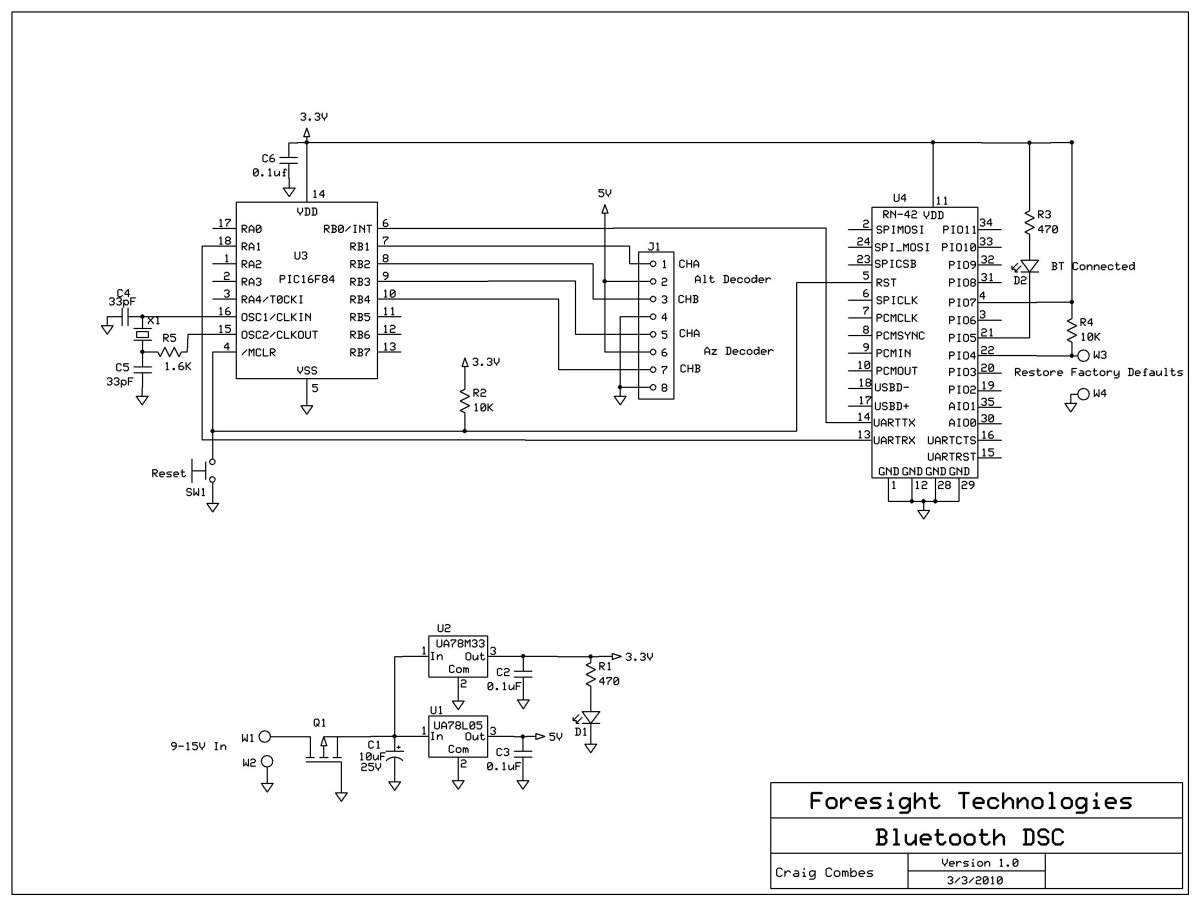
This variation of the Digital Setting Circles project was developed by Craig Combes, who shared his insights for others to replicate his version. Many users utilize Dave's serial DSC board along with a serial to Bluetooth adapter, which can...
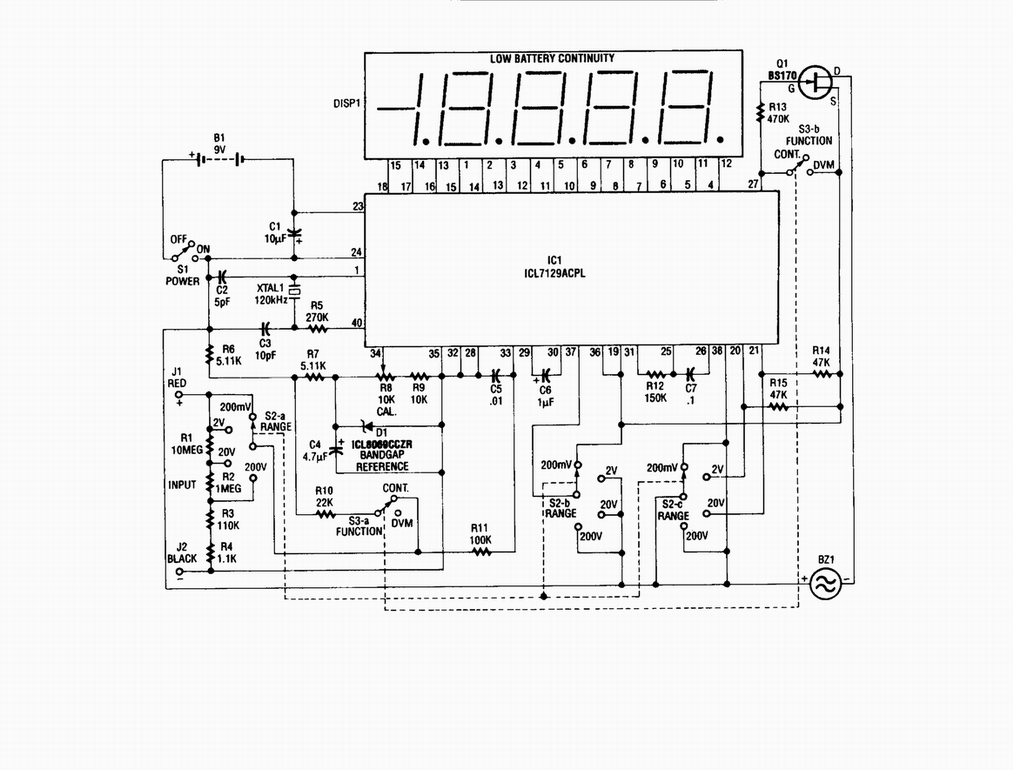
Single-chip digital voltmeter. This 4 1/2-digit DVM circuit is built around a Maxim ICL7129ACPL A/D converter and LCD driver. An ICL8069 CCZR 1.2-V band-gap reference diode is used for accuracy. The described circuit is a single-chip digital voltmeter (DVM) utilizing...
This digital volume control has no pot to wear out and introduces almost no noise in the circuit. Instead, the volume is controlled by pressing UP and DOWN buttons. This simple circuit would be a great touch to any...
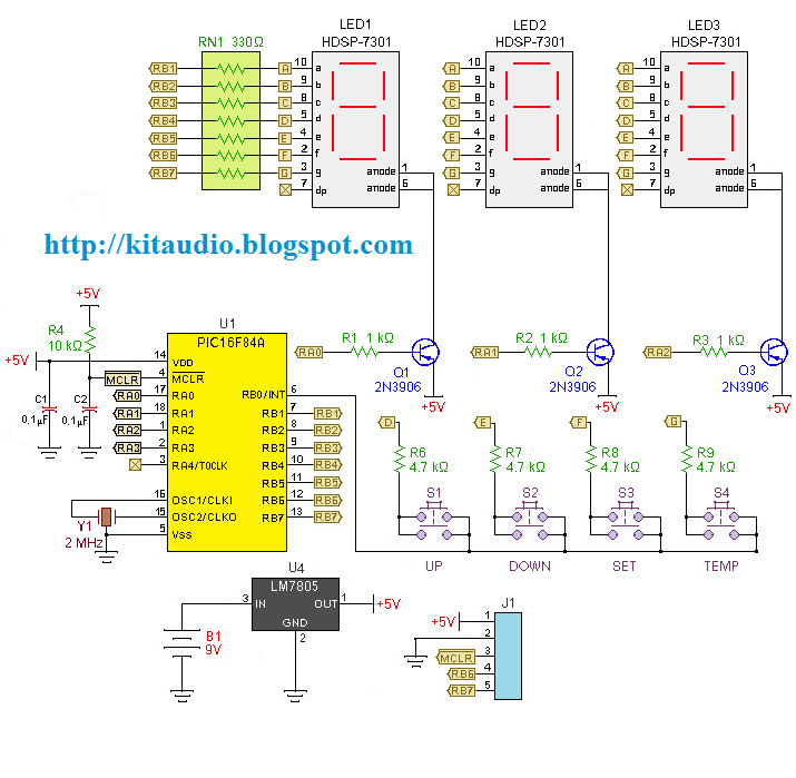
Redesign a complex solution using minimal external components, resulting in a low-cost application that provides high-precision measurements. This digital thermometer microcontroller project utilizes a watchdog timer function to measure temperature. The watchdog timer (WDT) on all PIC microcontrollers has...