
Digital capacitance meter
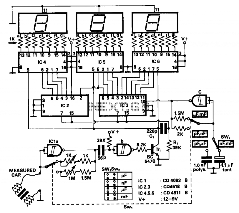
The described circuit operates as a capacitance measurement system utilizing an astable multivibrator configuration. The primary oscillator, represented by IC1c, is designed to produce a stable pulse train at a constant frequency. The frequency of this oscillator is critical as it serves as the reference for counting pulses. The lower frequency oscillator, represented by gate IC1a, is dependent on the variable capacitance C, which is the capacitor being measured. The relationship between the capacitance and the time period T of the oscillator is linear, allowing for accurate measurements of capacitance based on the timing characteristics.
The differentiator network, comprising resistor R1 and capacitor C1, plays a vital role in shaping the output signal from the oscillator. It generates a sharp negative spike in response to the leading edge of the pulse train. This negative spike is crucial as it triggers the NAND Schmitt Trigger (IC1b), which further conditions the signal into narrow pulses suitable for counting. The reset function of the counters ensures that each measurement cycle starts afresh, allowing for accurate counting of the pulses generated by the high-frequency oscillator.
The counting mechanism captures the number of pulses occurring within the time interval defined by the lower frequency oscillator. The display unit provides a visual representation of the counted pulses, which correlates directly to the capacitance value of the capacitor under test. This method of capacitance measurement is efficient and provides a digital output that is easy to read and interpret, making it suitable for various applications in electronic testing and measurement.The principle of operation is counting the pulse number derived from a constant frequency oscillator during a fixed time interval produced by another lower frequency oscillator. This oscillator uses the capacitor being measured as the timing. The capacitance measurement is proportional during pulse counting during a fixed time interval. The astable oscillator formed by IClc produces a pulse train of constant frequency. Gate ICla also forms an oscillator whose oscillation period is given approximately by the equation: T = 0.7 RC.
Period ? is linearly dependent on the capacitance C. This period is used.as the time interval for one measurement. The differentiator network following the oscillator creates the negative spikes shaped in narrow pulses by IClb NAND Schmitt Trigger. The differentiator formed by Rl and CI produces a negative spike which resets the counters. The display shows the number of high frequency oscillator pulses entering the counter during the measurement period.
🔗 External reference
Related Circuits
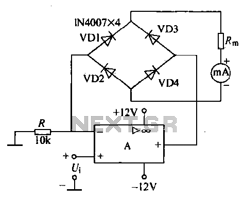
An operational amplifier, a diode bridge rectifier, and DC mA AC voltmeter tables are illustrated in the figure. The operational amplifier used is the LM324. The measured AC voltage is applied to the inverting terminal of the operational amplifier,...
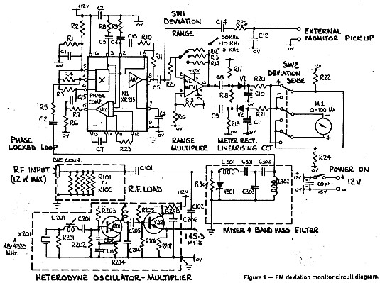
A deviation monitor can be constructed by connecting a frequency modulation (FM) detector to an AC voltmeter, calibrating the meter in units of frequency deviation. One method for detecting or demodulating the FM signal is via a phase-locked loop...
The circuit exhibits a flat frequency response ranging from approximately 20Hz to over 50kHz. The input sensitivity is set at 100mV for full-scale deflection on a 100µA meter. It is constructed using two common emitter amplifiers; the first stage...

A simple technique for measuring frequencies across a wide range with acceptable accuracy limits using a PC is presented. This method follows the basic principle of measuring low frequencies, where the period of a complete wave is measured and...
This circuit functions as a simple optical level indicator for sound signals, adaptable to various user needs. It allows for adjustments to input levels via trimmer potentiometers TR1 (Level) and TR2 (Gain). The signal is then rectified by diodes...

The micro ampere meter presented here functions as a DC millivolt meter. It achieves full-scale deflection with a 0.1V input. The current to be measured flows through a known resistance R, and the voltage drop across this resistance is...
Warning: include(partials/cookie-banner.php): Failed to open stream: Permission denied in /var/www/html/nextgr/view-circuit.php on line 713
Warning: include(): Failed opening 'partials/cookie-banner.php' for inclusion (include_path='.:/usr/share/php') in /var/www/html/nextgr/view-circuit.php on line 713