
Digital-Circuits
The CD4538 is a dual Monostable Multivibrator. When triggered, the chip generates a single pulse or a high-low event. The T+ pin (pin 4) of U1a serves as the positive edge trigger input, while the T- pin (pin 5) is the negative edge trigger input. When a falling edge is applied to pin 5, the output at pin 6 transitions from low to high, remaining high for a duration determined by the equation T = R2 * C1. The capacitors C1 and C2 can have values up to 33pF, and R2 can be adjusted to achieve the desired time constant, which should be significantly less than the period T of the crystal oscillator (T = 1/F). This configuration helps to filter out higher frequency components in the oscillator. The circuit described is a parallel resonant oscillator, where the crystal operates based on the piezoelectric principle, which alters the crystal's impedance in response to electric fields.
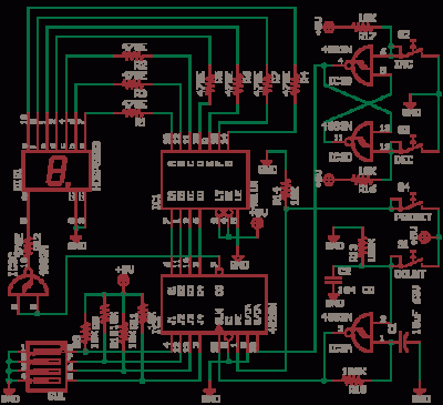
The U1 7555 is a CMOS version of the 555 timer, configured in Astable Oscillator mode. Capacitors C1 and C4 are used as decoupling capacitors with a value of 0.1µF (ceramic disc). The output frequency is approximately 100kHz, and using plastic or mica capacitors for C3 ensures frequency stability with temperature changes; however, a crystal oscillator is preferred for optimal performance. The output from the 555 timer feeds into the clock input of a CD4040 counter, producing a square wave output. On each falling edge of the square wave, the counter increments by one, yielding a 12-bit binary output.
Basic digital circuits such as Flip Flops and Counters are incorporated within this design. The circuit can be cascaded to create a 6-digit event counter or a simple frequency counter, with modern implementations often utilizing microcontrollers. Understanding the fundamentals of gates, flip flops, and counters is essential for designing custom microcontrollers on FPGAs.
In this setup, a seven-segment display is utilized, with momentary acting Inc, Dec, and Set buttons, while the Clk button is latching. A DIP switch is also included for additional configuration. The 555 Astable timer generates a clock signal for the circuit, producing a square wave output at pin 3 that is counted by a CD4017, creating a running lights effect. The CD4017 decade counter has 10 outputs, advancing one LED for each rising edge at the clock input. After completing one cycle, the first LED lights up again. The speed of the LED sequence can be adjusted using a 100K linear potentiometer for R2.
Some outputs are managed by the DS8830 Dual Differential Line Driver, which interfaces with standard TTL systems. This driver provides balanced differential outputs suitable for long-distance transmission over coaxial cables, strip lines, or twisted pair lines with characteristic impedances ranging from 50 to 500 ohms. Differential transmission effectively mitigates the impact of ground shifts and noise that may appear as common mode voltages on the transmission line. If the signal voltage at the line's end is inadequate, an additional circuit may be employed to amplify the signal.
The design also illustrates how to implement an OR gate using two 555 timers. When one 555 operates at a low frequency, it controls a valve, while the second 555 extends the duration of the ON pulse through a diode OR gate. The OR output utilizes a sample-and-hold mechanism to stabilize the analog data from a sensor after the actuator has turned off, ensuring accurate readings. The 555 timer is a versatile Mixed Signal Circuit that can be configured as a Voltage-Controlled Oscillator (VCO) using pin 5. Historical documentation from manufacturers like Exar often showcases the 555 timer alongside PLLs and tone decoders, highlighting its diverse applications in electronic design.CD4538 is a dual Monostable Multivibrator. When you trigger the chip the output sends off one single pulse or one high-low event. The T+ pin 4 of U1a is the positive edge trigger or raising edge trigger input, the T- pin 5 is falling edge or negative edge trigger input. Now see the image of the single pulse above which shows both the edges, If thi s is the input pulse at pin 5 then the falling edge turns the output pin 6 from low to high, this output remains high for time T = R2 * C1 and then goes Read More 74HCU04 is a chip that was made for this purpose, HCT may not work for such a circuit. C1 and C2 can go to upto 33pF and R2 can be increased to make R2 * C2 = t. Time constant much less than the period T of the crystal T = 1/F. This is to remove higher frequency components in the Oscillator. The circuit above is a parallel resonant oscillator circuit. The Crystal works by the piezoelectric principle, piezo means pressure. The electric field causes the impedance of the crystal to change. The LP Record Player needle is the Read More U1 7555 is a CMOS version of 555. The 555 here is in Astable Oscillator mode, C1 and C4 are decoupling capacitors 0. 1uF value, ceramic disc. The output is around 100kHz, If C3 is plastic or mica the frequency output will be stable with temperature.
It is better to use a crystal oscillator. The 555 output is fed to clock input of 4040, the output of 555 will be a square wave, on every high to low transition (falling edge or negative transition) the counter increments by one and the output is 12 bit binary. If input frequency is F Read More The basic digital circuits are Flip Flop and Counter, both are here.
This circuit can be cascaded to make even a 6 digit event counter, even a simple frequency counter can be made. These are best done with microcontrollers today. Then what if you have to design your own microcontroller on a FPGA, so the basics have to be sound, hence you have to know what gates, flip flops and counters are.
see the seven segment display. Inc, Dec, and Set buttons are momentary acting and Clk Button is latching type. The Dip Switch in the also can be set. Read More The 555 Astable generates a clock for this circuit, an oscillator giving a square wave output at pin 3 which is counted by 4017 to give a running lights effect. The decade counter-divider CD4017 has 10 outputs, for every low to high transition at the clock input, rising edge, the counter advances one LED.
After going one full circle the the first LED lights again and it goes on. You can vary the value of R2 100K Linear potentiometer to make LEDs run fast or slow. The frequency of oscillation of astable 555 is given as f = 1. 44 / Read More Some outputs are via Dual Differential Line Driver type DS8830. This device will interface with standard TTL systems. The differential outputs are balanced and are designed to drive long lengths of coaxial cable, strip line, or twisted pair transmission lines with characteristic impedances of 50 ohms to 500 ohms. Differential transmission is superior to single wire transmission in that it nullifies the effects of ground shifts and noise signals which appear as common mode voltages on the transmission line.
If the signal voltage at the end of the line is found to be of insufficient magnitude then the following circuit Read More This shows how to OR gate two 555, when one 555 cycles at a low frequency a valve turns on an off, the second 555 stretches the ON duration of the pulse with a diode OR gate. The OR output uses sample and hold to get the stable analog data from a sensor after the actuator has gone OFF, this ensures correct reading.
555 is a fundamental Mixed Signal Circuit as it can be made into a VCO using Pin-5. If you see old exar databooks, you can see 555 and PLL and Tone decoders all applications compiled in one Read More 🔗 External reference