
Digital Clock Circuit
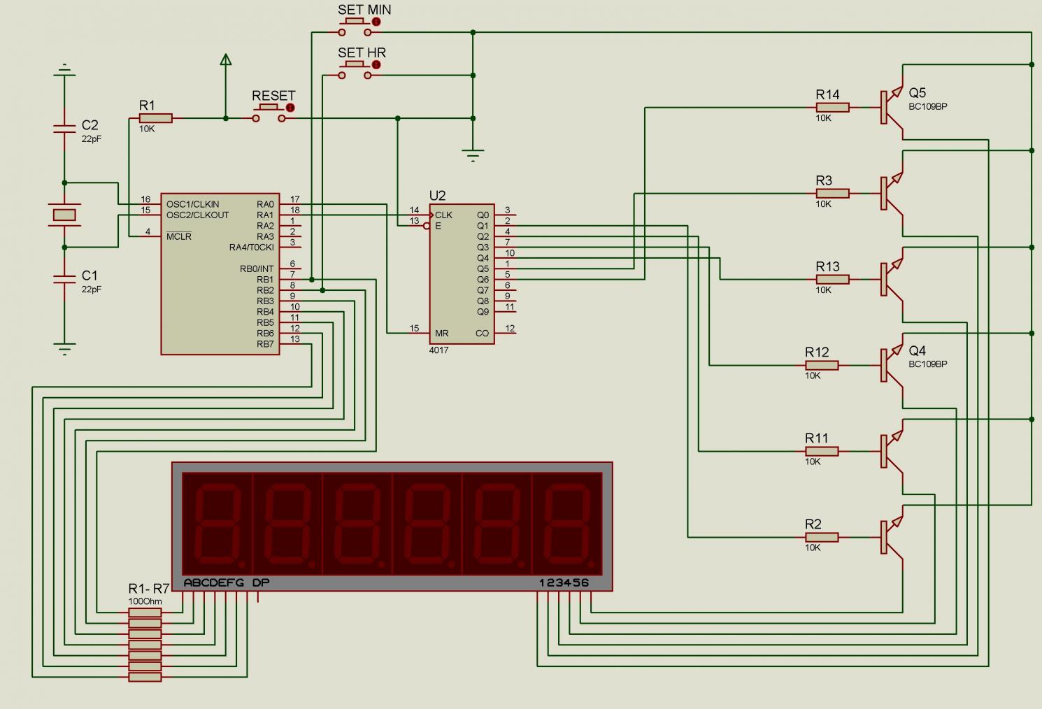
The circuit simulation in Proteus can often present challenges, especially for those who are new to the software or circuit design itself. Common issues may arise from component selection, incorrect connections, or simulation settings that are not properly configured.
To ensure successful simulation, it is important to verify the following aspects:
1. **Component Selection**: Ensure that all components used in the circuit are compatible with the simulation environment. Check the specifications of each component to confirm they are suitable for the intended application.
2. **Wiring and Connections**: Carefully inspect all connections within the circuit schematic. Miswiring or loose connections can lead to simulation errors. It is advisable to utilize the wire tool in Proteus to ensure that all nodes are properly connected.
3. **Power Supply**: Confirm that the power supply is correctly configured and connected to the appropriate components. An incorrect voltage or missing power supply can prevent the circuit from functioning as intended.
4. **Simulation Settings**: Review the simulation settings in Proteus. Ensure that the simulation mode (e.g., transient, AC analysis) is appropriate for the circuit being tested. Adjust the time step and simulation duration as necessary to observe the circuit's behavior effectively.
5. **Component Values**: Double-check the values assigned to resistors, capacitors, and other components. Incorrect values can lead to unexpected results in the simulation.
6. **Ground Connection**: Ensure that there is a common ground reference in the circuit. A missing ground can result in floating nodes, leading to simulation failures.
7. **Error Messages**: Pay attention to any error messages generated by Proteus during simulation. These messages can provide valuable insights into what may be causing the issue.
By systematically reviewing these elements, it is possible to identify and rectify the issues hindering the simulation process. This methodical approach will facilitate a better understanding of circuit behavior and improve proficiency with the Proteus simulation software.I`m having issues simulating this circuit on Proteus. Please take a quick look and make sure I did`nt make a goofy mistake. I`m also a novice with.. 🔗 External reference
Related Circuits
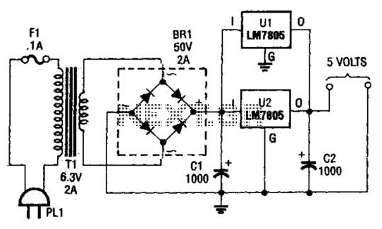
This DC supply is excellent for operating battery-powered antique radios, as it is designed to prevent damage to the tube filaments. The circuit is useful for powering the filaments of 00-A, 01-A, 112A, and 71A tubes, which require 5V...
P1 47K logarithmic potentiometer; P2, P3 47K linear potentiometers; R1, R3, R5 4.7K 1/4W resistors; R2 22K 1/4W resistor; R4 1M 1/4W resistor; R6 1.8K 1/4W resistor; R7 560Ω 1/4W resistor; C1, C4, C5, C7 10 µF 63V electrolytic...
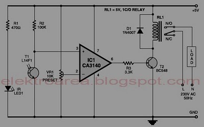
Typically, home appliances are controlled using switches, sensors, and similar devices. However, physical interaction with switches can pose safety risks in the event of a short circuit. The circuit outlined here eliminates the need for physical contact to operate...
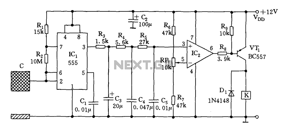
The switch circuit consists of a capacitive oscillator, an integration network, and a comparator circuit that controls a relay. When a body comes close to the induction plate, the inductive capacitance to ground increases, causing the 555 astable multivibrator...
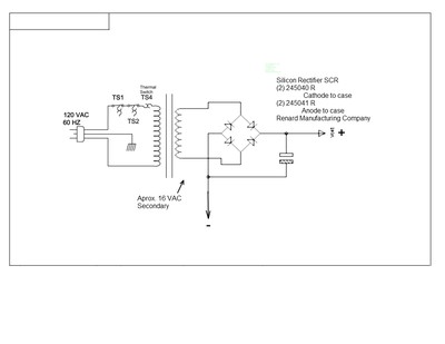
This document outlines a simple circuit diagram for a charger, utilizing a transformer, two SCRs, a capacitor, a heat sink, and a case for assembly. The circuit is designed for charging lead-acid batteries and can function even without the...
The following diagram is the circuit diagram of a 20W power amplifier built using the tube component EL34. The EL34 is a well-known tube, ideal for power tube amplifiers. The circuit presented is a complete design that includes both...
Warning: include(partials/cookie-banner.php): Failed to open stream: Permission denied in /var/www/html/nextgr/view-circuit.php on line 713
Warning: include(): Failed opening 'partials/cookie-banner.php' for inclusion (include_path='.:/usr/share/php') in /var/www/html/nextgr/view-circuit.php on line 713