
digital clock circuit
The Clock Controller circuit is designed to effectively manage the operation of a 7-segment LED display and keypad scanning through the use of a microcontroller programmed in 'C'. The primary function of this circuit is to utilize timer0 interrupts for precise timing control, allowing for the display of time or other data on the connected 7-segment display while simultaneously enabling keypad input scanning.
The circuit employs a common anode configuration for the 7-segment LEDs, where the anodes of the LEDs are connected to a positive voltage supply, and the cathodes are controlled by the microcontroller's output pins (P1.0 to P1.7). This configuration allows the microcontroller to sink current when a segment is activated, illuminating the respective segment of the display.
In addition to the LED control, the circuit incorporates a keypad interface, utilizing pins P3.0 to P3.3 to drive the base of four PNP transistors (such as the 2N2907). These transistors act as switches, enabling the microcontroller to manage the current flow through the keypad matrix. When a key is pressed, it completes a circuit that allows the microcontroller to detect the specific key pressed based on the row and column configuration of the keypad.
The design also includes provisions for driving external components such as relays or opto-triacs, providing flexibility for various applications. This is achieved through the 1-bit sink current output, which can effectively control these devices based on the logic output from the microcontroller.
Overall, the Clock Controller circuit serves as a foundational example for projects requiring integration of timekeeping, visual display through 7-segment LEDs, and user input through a keypad, making it a valuable reference for similar electronic designs.The Clock Controller was designed to be an exemplary of using 'C' language to control timer0interrupt, 7-segment LED and keypad scanning. It provides 1-bit sink currentdriving output, for driving a relay, opto-triac, say. Many projects requiring7-segment display and keypad interfacing may get the idea from the Clockcircuit and software.
Figure 1 shows a circuitdiagram of the Clock Controller V1.1. P10-P1.7 drives 7-segment commonanode LED with sink current. P3.0-P3.3 also drives a base pin of 4-PNPtransistor, 2n2907 with sink current. As shown in the figure, the 2nd 2-digitLED that conne 🔗 External reference
Related Circuits
This 1 Hz and 2 Hz generator or oscillator is constructed using a 4060 IC as the oscillator and a 14-bit counter. To achieve a 1 Hz signal from the 4060, a 1/2 4013 flip-flop is utilized. This circuit...
Discharge before memory circuit. Before the memory circuit is activated, a delay reset circuit is required. When the input signal triggers an action, timing begins, and after a specified delay, the circuit reverts to its original state. During this...
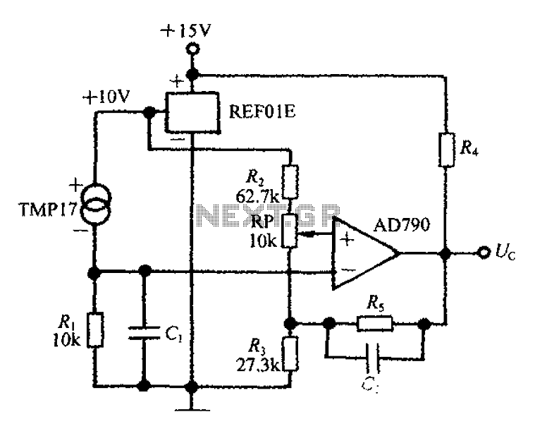
An adjustable thermostat controller circuit is widely used in everyday applications, such as for maintaining a constant temperature in soldering irons. The circuit utilizes the TMP17 sensor along with the REF01E voltage reference to ensure a stable 10V supply...
The LM3886 amplifier electronic circuit project is designed to deliver 68W of continuous average power into a 4-ohm load and 38W into an 8-ohm load with a total harmonic distortion plus noise (THD+N) of 0.1% across the frequency range...
The electronic designs for the two animatronic mouths are presented below. The first design is for the articulated mouth, with additional servos for the eyebrows and eyes. The second design is for the LCD mouth, which closely resembles the...
The current loop interface circuit diagram of the AD694 multi-functional sensor signal conditioner is utilized as a digital-to-analog converter (DAC). This current loop interface enables the conversion of digital values into voltage and subsequently into current signals. The circuit...