
Digital Clock Circuit with T89C51 microcontroller
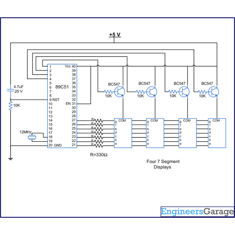
The digital clock circuit primarily involves the AT89C51 microcontroller, which serves as the central processing unit for timekeeping and display control. The four seven-segment displays are arranged to represent the time in the format of MM:SS (minutes and seconds). Each display consists of 7 segments plus a decimal point, and the common anode configuration allows for easy control of the segments by turning them on or off through the microcontroller.
The multiplexing technique is critical in this design, as it reduces the number of pins required for control while maintaining a clear display. By rapidly switching between the displays, the human eye perceives all segments as lit simultaneously due to persistence of vision. The Timer0 interrupt is configured to trigger at a specific frequency, allowing the microcontroller to manage the timing of the display updates effectively.
Timer1 is utilized to create a precise one-second delay, ensuring accurate timekeeping. The microcontroller's internal clock frequency determines the timer settings, which must be calibrated to achieve the desired timing accuracy. The connection of the segment data pins to port P2 allows the microcontroller to send the appropriate signals to illuminate the correct segments for each digit displayed.
The control pins connected to port P1 enable the microcontroller to activate the correct display at any given time, ensuring that only one display is on at a time while the others remain off. This minimizes power consumption and avoids ghosting effects on the displays. The logic implemented within the microcontroller firmware handles the counting of seconds, minutes, and the transition between them, effectively managing the timekeeping process.
Overall, this digital clock circuit is a practical application of microcontroller technology, demonstrating the integration of hardware and software to create a functional timekeeping device suitable for various environments.A digital clock is one that displays time in digital format. The circuit described here shows the time with double-digit "minutes" and two digits `seconds` in four seven segment displays. The segment of seven switches are interconnected with 8051 microcontroller AT89C51. This circuit can be used in vehicles, homes, offices and many others. At the time of the source Vcc is supplied to this circuit, the clock starts from 00:00. The time is displayed in four segments of 7 (in the common anode configuration) using the notion of multiplexing. That is achieved by using the timer interrupt (Timer0) of AT89C51 is set to update the 7-segment. The segments are updated several times in the second to be displayed simultaneously. The clock is ticking, which is delayed by one second with single precision. Timer1 is used to produce a one second delay. The pins of information (h) of the many segments are interconnected and get P2 port signal to the microcontroller.
The control or enable pin (anode popular) are connected to pins 1-4 of port P1 3). The number in the fourth section (which shows the unity of the digits 2 ) increases as early as the second, and from 0 to nine. The range in the third section increases immediately after every 10 seconds from 0 to 5. Therefore, the seconds are different sample of 00 to 59. The digit of the variations of the second section after every 60 seconds (one minute) from 0 to nine, etc.
So the clock is ticking for an hour and after it resets again 🔗 External reference
Related Circuits
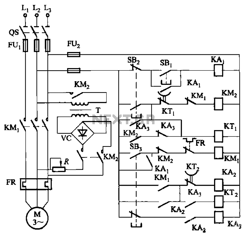
The circuit depicted in Figure 3-143 demonstrates a braking mechanism for a motor that operates effectively during normal shutdown and jog operations. The circuit includes several components, such as the start button (SBz), stop button (SBz), and jog button...
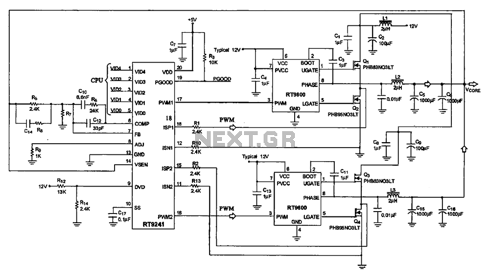
A typical computer motherboard CPU power supply circuit is primarily composed of the main power supply management chip RT9241 and additional components from the power management chip RT9600. The voltage command signal from the CPU is input into the...
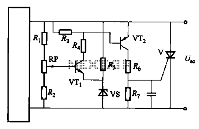
Both circuits are designed solely for overcurrent protection in power supply applications. The circuits in question serve as critical components in safeguarding power supply systems from overcurrent conditions. Overcurrent protection is essential in preventing damage to electrical components and...
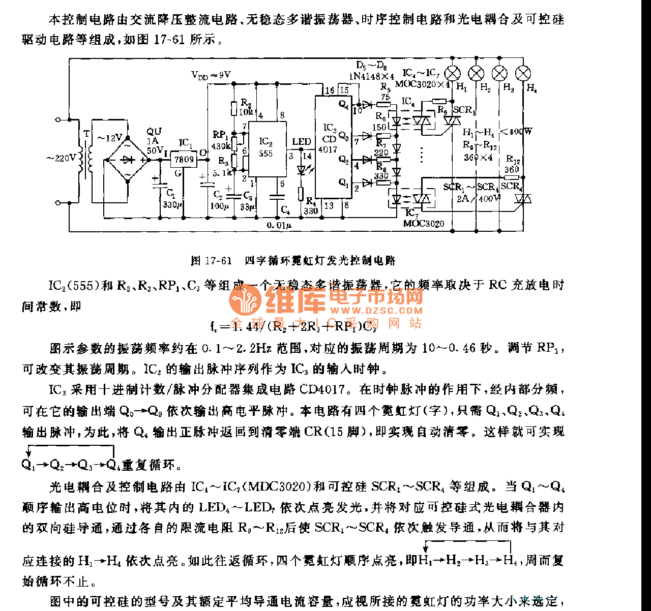
This control circuit consists of an AC step-down rectifier circuit, an astable multivibrator, a timing control circuit, an optocoupler circuit, and an SCR driving circuit, as illustrated in Figure 17-61. The astable multivibrator is formed using IC2 (555), resistors...
The PowerSaver Flasher uses capacitive output coupling to produce brighter shorter flashes and has a much lower average current drain than standard bicore or 74HC14 flashers. The PS Flasher with one LED circuit (2 LEDs) runs all night from...
This application note analyzes the details of a Wien-bridge oscillator, shows how a JFET maintains oscillation, and demonstrates adding a digital potentiometer (digipot), rather than a variable resistor, to improve stability and flexibility. The Wien-bridge oscillator is a type of...
Warning: include(partials/cookie-banner.php): Failed to open stream: Permission denied in /var/www/html/nextgr/view-circuit.php on line 713
Warning: include(): Failed opening 'partials/cookie-banner.php' for inclusion (include_path='.:/usr/share/php') in /var/www/html/nextgr/view-circuit.php on line 713