
Digital code Lock with AT89C2051
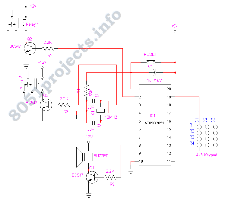
The described digital lock system utilizes the AT89C2051 microcontroller, which is pivotal in managing the access control functionality. The microcontroller features an 8-bit architecture and is equipped with 2KB of ROM, allowing for the storage of the control program. The system is designed to enhance security by ensuring that only users with the correct password can gain access to restricted areas.
The password management is facilitated through an EEPROM (Electrically Erasable Programmable Read-Only Memory), which provides the flexibility to modify the stored password without requiring physical access to the microcontroller. This feature is essential for maintaining security, as it allows for regular updates to the access credentials.
A keypad interface is integrated into the system, enabling users to input their passwords. The keypad typically comprises a matrix arrangement of keys, which allows for efficient data entry. Upon entering a password, the microcontroller compares the input against the stored password in the EEPROM. If the entered password matches the stored password, the microcontroller activates a relay.
The relay serves as an electronic switch that controls the locking mechanism of the door. When the relay is energized, it allows current to flow to the locking mechanism, thereby unlocking the door and granting access to the authorized user. Conversely, if the password does not match, the relay remains deactivated, and the door remains locked, preventing unauthorized access.
To further enhance the security and functionality of the system, additional features may be incorporated. These can include visual indicators such as LEDs to signal the status of the lock (locked/unlocked) and audible alerts for incorrect password entries. Moreover, the system can be designed to include a timeout feature that temporarily disables access after a certain number of failed attempts, thus mitigating the risk of brute-force attacks.
In summary, the microcontroller-based digital lock system provides a robust solution for access control, leveraging the capabilities of the AT89C2051 microcontroller, EEPROM for password storage, and a user-friendly keypad interface to ensure secure and reliable operation in restricting access to designated areas.Security is a prime concern in our day-today life. Everyone wants to be as much secure as possible. An access control for doors forms a vital link in a security chain. The microcontroller based digital lock for Doors is an access control system that allows only authorized persons to access a restricted area. The system is fully controlled by the 8 bit microcontroller AT89C2051 which has a 2Kbytes of ROM for the program memory.
The password is stored in the EPROM so that we can change it at any time. The system has a Keypad by which the password can be entered through it. When the entered password equals with the password stored in the memory then the relay gets on and so that t 🔗 External reference
Related Circuits
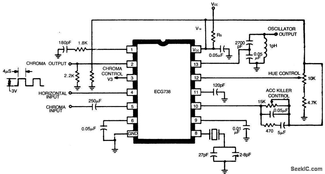
Color TV chroma processor with automatic color control (ACC), color killer, and an injection lock reference system. The typical power supply voltage is between 9 to 11.5 volts. The hue control range is 100 degrees. The oscillator output signal...
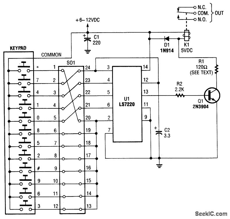
A keypad is used to input a four-digit access code, which can be programmed using jumpers on a 24-pin plug-in header and socket. The component U1 is an LST220, responsible for detecting the sequential four-digit data input. Upon entering...
The function generator features two BNC outputs: one for the high speed [1 to 8 MHz] square signal (BNC1) and another for the DDS signal (BNC2). Offset and amplitude can be regulated by two potentiometers: offset in range of...
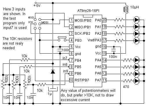
Study the Analog to Digital capabilities of Atmel ATtiny26. This tiny but mighty IC is really a miracle. One special thing is the internal 10-inputs multiplexed ADC circuit which can convert analog voltages to bytes. This check circuit uses...
A schematic for a code practice oscillator is needed, which can be connected to a keyer. The desired setup involves using a Picokeyer, allowing the oscillator to be plugged into the key jack of the Picokeyer. The output should...
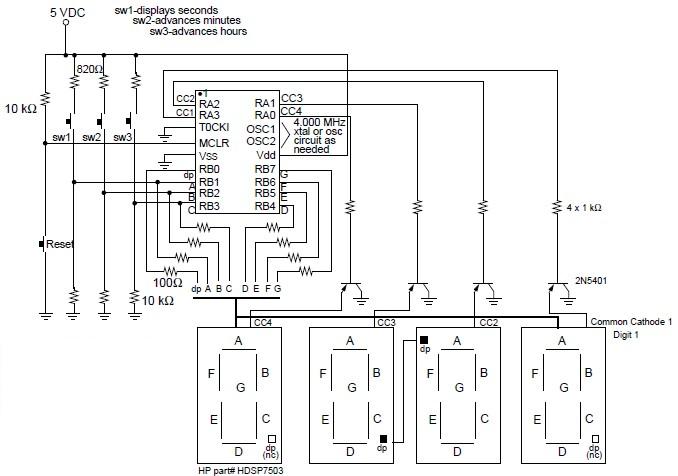
A digital clock project utilizing the PIC16C54 microcontroller can be constructed using the provided circuit diagram. This electronic project features a time-of-day clock that includes four seven-segment LED displays and three input switches. Additionally, there is a reset switch...
Warning: include(partials/cookie-banner.php): Failed to open stream: Permission denied in /var/www/html/nextgr/view-circuit.php on line 713
Warning: include(): Failed opening 'partials/cookie-banner.php' for inclusion (include_path='.:/usr/share/php') in /var/www/html/nextgr/view-circuit.php on line 713