
Digital-frequency-window
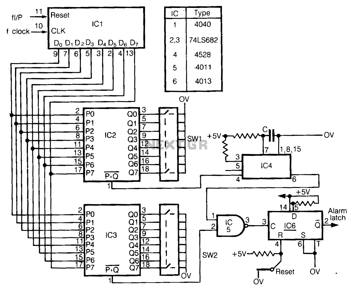
This circuit detects frequency variations that exceed preset limits. IC1 functions as a binary counter connected to the clock frequency (FcLK). The outputs from IC1 are compared with preset values set by IC2 and IC3. The input signal, which must be a positive-going pulse, is utilized to reset IC1. The output indicating when P is greater than Q from the comparators is at logic 0 for input frequencies below the preset values. When the input frequency exceeds the preset count, a pulse train is generated. IC2 detects a low input by providing the pulse train to a retriggerable monostable, IC4. If the input frequency drops below the preset value defined by SW1, the monostable is no longer triggered, resulting in its output dropping to logic 0. IC3 detects when the frequency is in a high state as set by SW2, and it outputs directly when this condition is met. The outputs from both comparators can be latched as illustrated, using IC5 and IC6. The clock frequency is related to the input signal and switch values: switch value is approximately equal to FcLK multiplied by the input. The time constant of IC4 is not critical but must exceed the maximum input pulse period.
This circuit is designed to monitor frequency variations and respond accordingly based on predetermined thresholds. The core component, IC1, serves as a binary counter that counts the clock pulses from FcLK. The counting mechanism allows for real-time monitoring of the input frequency, which is essential for applications requiring precise frequency detection.
IC2 and IC3 are comparator circuits that compare the output of IC1 with the preset values set by the switches SW1 and SW2. The output from these comparators indicates whether the input frequency is below or above the defined thresholds. When the input frequency is below the threshold set by SW1, the output of the comparator will be at logic 0, indicating a low frequency state. Conversely, when the frequency exceeds the threshold, a pulse train is generated, signaling that the frequency is high.
The retriggerable monostable IC4 plays a crucial role in this circuit by providing a time delay based on the input frequency. If the frequency drops below the preset value, IC4 ceases to trigger, causing its output to fall to logic 0. This output can be used to signal other parts of the circuit or to initiate further actions based on the detected frequency change.
IC3 operates similarly, monitoring for high-frequency states as defined by the switch SW2. When a high frequency is detected, IC3 outputs a signal that can be utilized for further processing or control functions.
The use of IC5 and IC6 for latching the outputs from the comparators allows for stable outputs that can be used in decision-making processes or to trigger alarms and notifications. The design ensures that the circuit can effectively respond to a range of frequency inputs, making it suitable for various applications in frequency monitoring, control systems, and automated responses in electronic systems.
Overall, this frequency detection circuit is a robust solution for applications requiring precise frequency monitoring and response, with the flexibility to accommodate various input signals and preset thresholds.This circuit detects frequency variation above or below preset limits. IC1 is a binary counter docked at FcLK· The outputs are comparea with switch preset values by IC2 and IC3. The input signal, which must be a positive-going pulse, is used to reset IC1. The P greater than Q output of the comparators is at logic 0 for input frequencies below the preset values.
Above the preset count, a pulse train is output. IC2, detects a low input by supplying the pulse train to a retriggerable monostable, IC4. When the input frequency falls below the preset value in SWl, the monostable is no longer triggered and its output falls to logic 0. IC3 detects the frequency high state SW2, and outputs directly when this occurs. The outputs from both comparators can then be latched as shown, using IC5 and IC6. The clock frequency is related to input and switch values: switch value ~ FcLK!i,put· The time constant of IC4 is not critical, but must obviously exceed the maximum input pulse period.
🔗 External reference