
Digital-ir-transmitter
Gates U1a and U1b are configured as a low-frequency oscillator. The output waveform at pin 11 is nonsymmetrical, with the positive portion of the signal comprising only 20% of the time period. Diode D1, a 1N914 general-purpose unit, along with capacitors C1 and resistors R1 and R2, determines the duration of the positive portion of the output waveform. The negative portion of the output waveform primarily depends on the values of R1 and C1. The operating frequency of this oscillator is approximately 11 Hz. The second oscillator consists of U1c and U1d, which produces an almost symmetrical waveform at a frequency of about 400 Hz. The output of the first oscillator (U1a/U1b) is fed to pin 8 of U1c to control the second oscillator (U1c/U1d) on and off at about 11 Hz, with the on time limited to around 20% of the time period (approximately 15 ms). The output waveform of the second oscillator is directed to the base of transistor Q1, which drives infrared diode LED1 in short bursts. Pulsing LED1 aids in conserving battery power and allows each circuit to have its unique sound footprint. By modifying any of the values of R1, R2, R3, C1, or C2, the sound footprint can be adjusted. Increasing the component values decreases the oscillator's frequency, while decreasing the values increases the frequency.
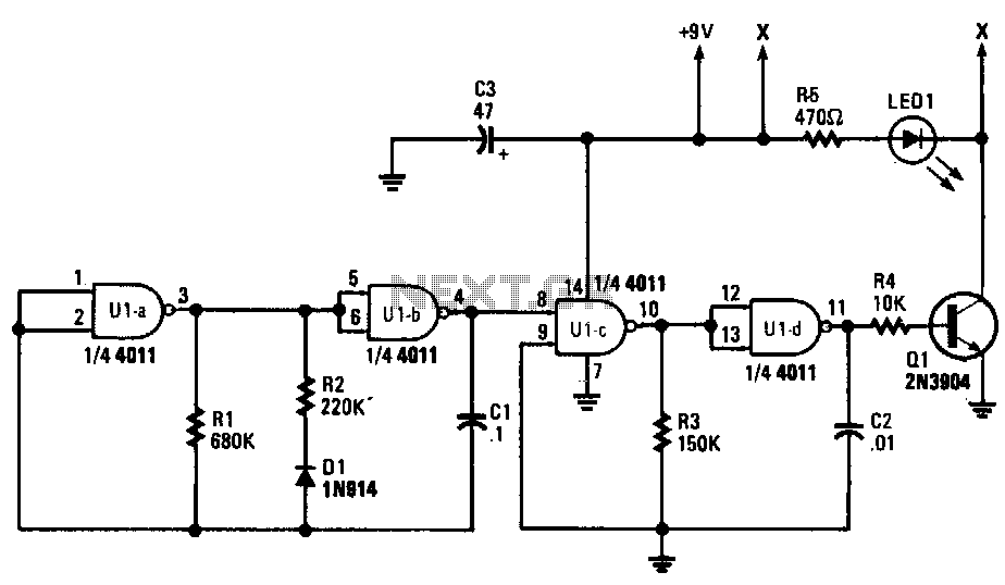
Gates U1a and U1b function as the primary low-frequency oscillator within the circuit, generating a nonsymmetrical output waveform at pin 11. The waveform's positive portion, which lasts for only 20% of the total time period, is influenced by the arrangement of diode D1 (1N914), capacitor C1, and resistors R1 and R2. The negative portion of the waveform is primarily determined by the values of R1 and C1, establishing the timing characteristics of the oscillator.
Operating at an approximate frequency of 11 Hz, this oscillator is complemented by a secondary oscillator composed of U1c and U1d. This second oscillator generates an almost symmetrical output waveform at a significantly higher frequency of about 400 Hz. The output from the first oscillator is connected to pin 8 of U1c, enabling it to control the second oscillator's operation in an on/off manner at the same frequency of 11 Hz. The on time for this second oscillator is limited to around 20% of its cycle, equating to approximately 15 ms.
The output from the second oscillator is directed to the base of transistor Q1, which is responsible for driving the infrared diode LED1 in short bursts. This pulsing action is advantageous for battery conservation, as it minimizes power consumption while providing the circuit with a distinct sound footprint. The sound footprint can be customized by altering the values of resistors R1, R2, R3, and capacitors C1 and C2. An increase in these component values results in a reduction of the oscillator's frequency, while a decrease leads to an increase in frequency, allowing for versatile sound modulation within the circuit.Gates U1a and U1b are configured as a low-frequency oscillator. The output waveform at pin 11 is nonsymmetrical with the positive portion of the signal, making up only 20% of the time period. Diode D1, a 1N914 general-purpose unit, together with C1, R1, and R2, determine the on time for the positive portion of the output waveform.
The off, or negative portion of the output waveform, depends mainly on the values of R1 and Cl. The operating frequency of that oscillator is about 11 Hz. The second oscillator consists ofU1c and U1d, which outputs on almost symmetrical waveform at a frequency of about 400Hz. The output of first oscillator U1a/U1b is fed to pin 8 of U1c to key second oscillator U1c/U1d on and off at about 11 Hz, with the on time limited to about 20% of the time period (about 15 ms).
The output waveform of the second oscillator is fed to the base of Q1, which is used to drive IR diode LED1 in short bursts. Pulsing LED1 helps to save battery power, and also allows each circuit to be given its own special sound footprint.
By changing any of the values of Rl, R2, R3, Cl, or C2, the sound footprint can be varied. As the component values are increased, the oscillator"s frequency goes down, and as the values are decreased, the frequency goes up. 🔗 External reference