
digital oscilloscope
The described early test program utilizes assembly language, which is a low-level programming language that provides a symbolic representation of a computer's machine code. Assembly language is closely related to the architecture of the computer's CPU, allowing for direct manipulation of hardware components. The program is stored in an EEPROM, a type of non-volatile memory that retains data even when power is removed. This characteristic makes EEPROM a suitable choice for applications where data integrity is crucial, such as firmware storage or configuration settings.
In this context, the program likely serves as a preliminary test to verify the functionality of the EEPROM and the associated circuitry. The assembler programming used in this case allows for precise control over the hardware, enabling the programmer to write instructions that directly correspond to machine operations. Each instruction in the assembly code corresponds to a specific binary operation, providing a more readable format for developers compared to raw binary coding.
The use of assembly language in conjunction with EEPROM technology highlights the importance of understanding both hardware and software interactions in embedded systems. The programmer can optimize performance and resource utilization by writing efficient assembly code, ensuring that the program runs effectively within the constraints of the hardware. This foundational knowledge is essential for developing more complex applications and systems that rely on low-level programming techniques.This is an early test program (assembly source code), which was stored on the erasable programmable memory chip (EEPROM). Assembler programming is just 1 step above programming at the binary level. 🔗 External reference
Related Circuits
This chapter shows how to connect an analogue signal to a PIC. An analogue signal is similar to a sine wave and is generally less than 5v (5,000mV) in amplitude. Low-level signals are generally expressed in mV, to make...

This circuit is a simple DC to DC converter designed for digital circuits. It operates with a supply voltage of 5V and provides an output voltage that steps up to a maximum of 10V-12V DC. The circuit utilizes an...
The clock timer utilizes a PIC16F628 microcontroller to display time in a 3.5-digit format and manage an external load. It features a calendar that accounts for leap years and optional daylight saving time adjustments. The timer output can be...
The digital readout of the Corsair 560 is positioned above the tuning knob. In this radio, the six-digit display often fluctuated, frequently doubling the frequency indication. The reading was unstable, making it challenging to determine the tuned frequency. After...
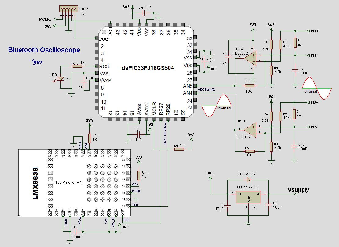
The transmitter circuit utilizes Microchip's dsPIC33FJ16GS504 for analog-to-digital conversion of input signals on two channels. The processed data from the dsPIC is transmitted to a mobile phone for waveform display via the LMX9838 Bluetooth SPP module. The source code...
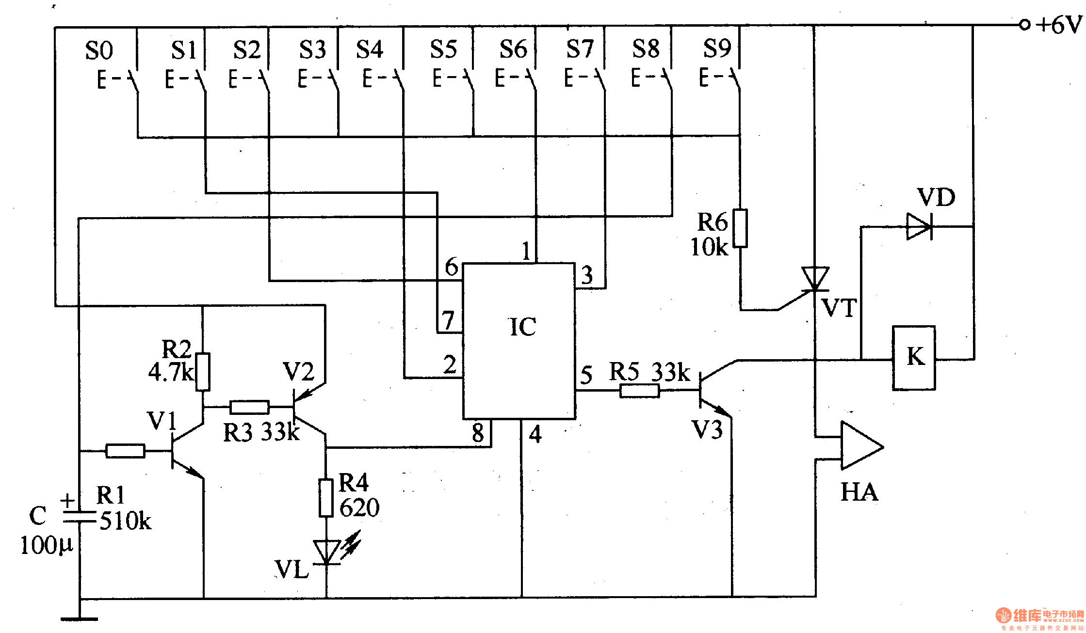
The digital lock circuit consists of a timing trigger circuit, a trick lock circuit, a sound and alarm circuit, and a control implementation circuit, as illustrated in Figure 3-101. The timing trigger circuit is made up of transistors V1...