
Digital-peak-detector
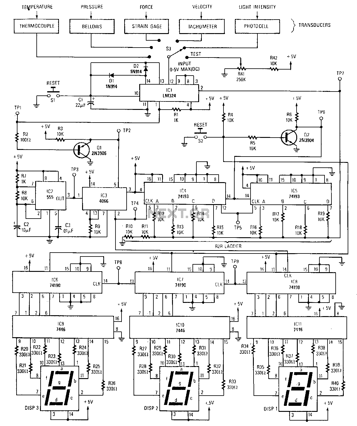
The peak detector tracks and holds the highest output voltage from a transducer by utilizing the charge-storing capability of a capacitor. Initially, the voltage at the inverting input of the comparator is at ground level. When a small voltage (0-5 V) is captured by the peak detector and presented to the non-inverting input of the comparator, the output will swing high, activating the bilateral switch. This allows clock pulses to pass through the switch, thereby clocking both the BCD and binary counters. The outputs from the binary counters are connected to an R2R ladder network, which serves as a digital-to-analog converter. As the binary count increases, the voltage from the R2R ladder also rises until it surpasses the voltage level of the peak detector. At this moment, the comparator output swings low, disabling the bilateral switch and halting the counters. The number displayed on the 7-segment LEDs represents a value equivalent to the output from the transducer.
The described circuit operates as a peak detection system integrated with digital counting and analog conversion functionalities. The peak detector's primary role is to capture and hold the maximum voltage from a transducer, which may be a sensor providing varying voltage levels corresponding to physical phenomena (e.g., temperature, pressure, or light intensity). The capacitor in the peak detector serves as a storage element, maintaining the highest voltage level detected until it is reset or until a higher voltage is detected.
The comparator is a crucial component in this circuit, comparing the voltage levels at its two inputs. The use of a bilateral switch allows for the controlled passage of clock pulses to the counters only when the detected voltage is above a certain threshold, ensuring that the counting process is synchronized with the peak detection. The binary counters convert the digital signals into a binary format, which is then processed by the R2R ladder network. This network is a type of digital-to-analog converter (DAC) that translates the binary output into a corresponding analog voltage.
The R2R ladder network consists of resistors arranged in a specific configuration that determines the output voltage based on the binary input. As the count increases, the output voltage from the R2R ladder rises until it reaches a level that triggers the comparator to deactivate the bilateral switch. This mechanism effectively stops the counting process, ensuring that the final count displayed on the 7-segment LED reflects the maximum voltage detected by the peak detector.
The overall design is efficient for applications requiring real-time monitoring and display of varying analog signals, providing a visual representation of the transducer's output through the 7-segment display. This circuit, designed by Mr. Roger D. Secura, exemplifies a practical approach to integrating peak detection, digital counting, and analog conversion in a cohesive electronic system.The peak detector tracks and holds, using the charge-storing ability of a capacitor, the highest output voltage from a transducer. Initially, the voltage on the inverting input of the comparator is at ground level. As a small voltage (0-5 V) is captured by the peak detector and presented to the comparator"s noninvert· ing input, the output will swing high, which asserts the bilateral switch; clock pulses now pass through the switch to clock both the BCD and binary counters.
The outputs of the binary counters are connected to an R2R ladder network, which functions as a digital-to-analog converter. The author of this great circuit is Mr. Roger D. Secura.
🔗 External reference
The described circuit operates as a peak detection system integrated with digital counting and analog conversion functionalities. The peak detector's primary role is to capture and hold the maximum voltage from a transducer, which may be a sensor providing varying voltage levels corresponding to physical phenomena (e.g., temperature, pressure, or light intensity). The capacitor in the peak detector serves as a storage element, maintaining the highest voltage level detected until it is reset or until a higher voltage is detected.
The comparator is a crucial component in this circuit, comparing the voltage levels at its two inputs. The use of a bilateral switch allows for the controlled passage of clock pulses to the counters only when the detected voltage is above a certain threshold, ensuring that the counting process is synchronized with the peak detection. The binary counters convert the digital signals into a binary format, which is then processed by the R2R ladder network. This network is a type of digital-to-analog converter (DAC) that translates the binary output into a corresponding analog voltage.
The R2R ladder network consists of resistors arranged in a specific configuration that determines the output voltage based on the binary input. As the count increases, the output voltage from the R2R ladder rises until it reaches a level that triggers the comparator to deactivate the bilateral switch. This mechanism effectively stops the counting process, ensuring that the final count displayed on the 7-segment LED reflects the maximum voltage detected by the peak detector.
The overall design is efficient for applications requiring real-time monitoring and display of varying analog signals, providing a visual representation of the transducer's output through the 7-segment display. This circuit, designed by Mr. Roger D. Secura, exemplifies a practical approach to integrating peak detection, digital counting, and analog conversion in a cohesive electronic system.The peak detector tracks and holds, using the charge-storing ability of a capacitor, the highest output voltage from a transducer. Initially, the voltage on the inverting input of the comparator is at ground level. As a small voltage (0-5 V) is captured by the peak detector and presented to the comparator"s noninvert· ing input, the output will swing high, which asserts the bilateral switch; clock pulses now pass through the switch to clock both the BCD and binary counters.
The outputs of the binary counters are connected to an R2R ladder network, which functions as a digital-to-analog converter. The author of this great circuit is Mr. Roger D. Secura.
As the binary count increases, the R2R ladder voltage also increases until it reaches a point slightly above the voltage of the peak detector; at that instant, the comparator output swings low, which disables the bilateral switch and stops the counters. The number displayed on the 7-segment LED"s will represent a value equivalent to the transducer"s output.
🔗 External reference