
Digital precision pressure tester circuit integrated precision pressure signal conditioner MAX1457
The digital precision pressure tester circuit is designed to provide accurate pressure measurements through a systematic approach involving various components. The MAX1457 serves as the core of the circuit, integrating functions necessary for processing pressure signals. The selection of the 93C66 E2PROM allows for external memory capabilities, facilitating the storage of calibration data and other essential parameters.
The circuit is powered by a stable +5V supply, ensuring consistent performance. The 400k ohm RBIAS resistor is critical in establishing the appropriate bias voltage, which is essential for the proper operation of the bias circuit. Decoupling capacitors C2, C4, and C6 are strategically placed to filter out high-frequency noise, maintaining signal integrity throughout the circuit. Bypass capacitors C1, C3, C5, C7 through C11 further enhance stability by providing localized energy storage, thus ensuring that the voltage levels remain stable during operation.
The excitation current of 0.5mA, established by the 50k ohm RISRC resistor, is vital for the sensor's operation, as it determines the sensitivity and response time of the pressure measurement. The RSTC resistor plays a crucial role in compensating for temperature-induced variations in the full-scale output, thus enhancing the accuracy of the readings across different environmental conditions. Meanwhile, the R*LIN resistor, although not adjustable, is essential for addressing non-linearities in the sensor's output, ensuring that the pressure values displayed on the DVM are as precise as possible.
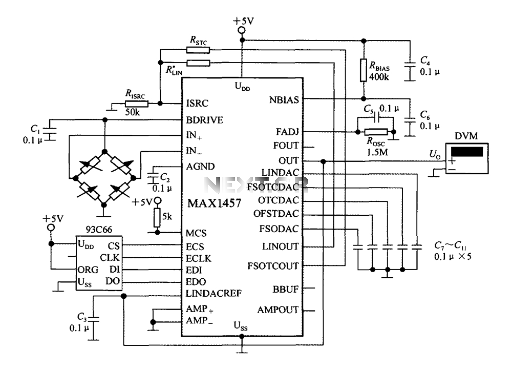
The output from the MAX1457 is directed to a digital voltmeter, which translates the processed pressure signal into a readable format. This setup allows for real-time monitoring of pressure values, making it suitable for various applications in industrial and laboratory settings where precision is paramount. Overall, the design of this digital precision pressure tester circuit reflects a comprehensive understanding of electronic principles and component functionality, resulting in an effective solution for pressure measurement.Digital precision pressure tester circuit shown in Fig. MAX1457 external ROM selection 93C66 type 4096b E2PROM. After power MCS end is pulled to a high level, check the main ch ip. + 5V power supply through a resistor RBIAS (400k ) provide appropriate bias voltage to the bias circuit. C2, C4 and C6 are decoupling capacitors. C1, C3, C5, C7 ~ C11 are bypass capacitors. When taking RISRC 50k, excitation current 0.5mA. RSTC full scale temperature coefficient compensation resistor, R * LIN non-linear calibration resistor (can not).
Pressure signal generated by the sensor after MAX1457 processing output from OUT terminal to the digital voltmeter (DVM), shows the measured pressure values.
Related Circuits
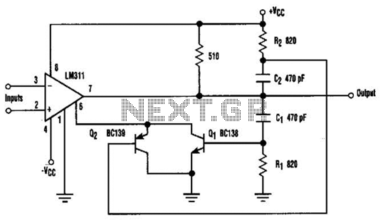
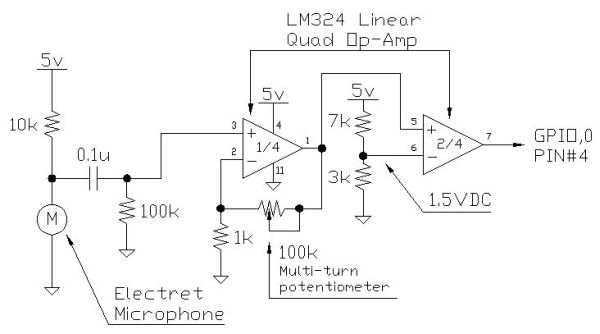
When the comparator's output transitions from low to high, the rising edge of the output pulse, differentiated by the Cl/Rl chain, activates Ql. This action blocks the comparator via its strobing input and maintains its output state for a...
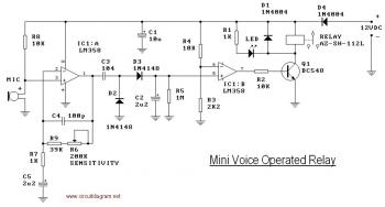
This circuit diagram illustrates a voice-operated relay, which functions similarly to a sound-activated switch circuit. It activates and deactivates the switch based on sound input. The output switch of this circuit is controlled by a relay. The release time...
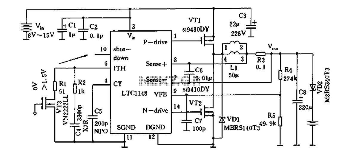
Efficient nickel-cadmium battery charger IC (LTC1148) circuit The LTC1148 is an integrated circuit designed for the efficient charging of nickel-cadmium (NiCd) batteries. This charger IC features a constant current/constant voltage (CC/CV) charging method, which is essential for optimizing the charging...
Instructions for creating a Clap-Clap On/Clap-Clap Off switch circuit. This guide provides the necessary information for constructing a clap-activated switch. The Clap-Clap switch circuit is an innovative design that utilizes sound activation to control electronic devices. The primary components of...
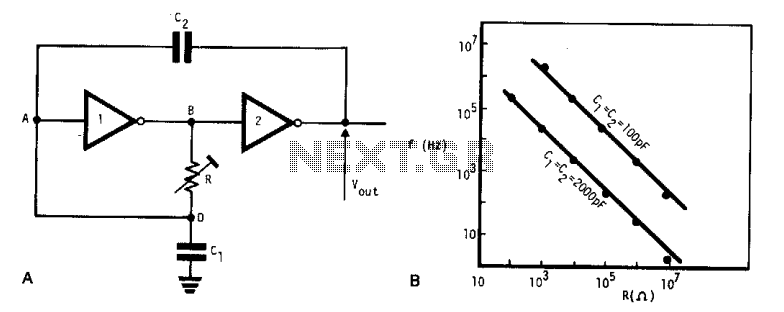
This simple, low-cost oscillator is constructed using two CMOS buffer inverters, two capacitors, and a variable resistor. The circuit operates with voltage levels ranging from 4 V to 18 V. When C1 equals C2, the frequency of oscillation is...
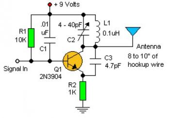
Experimenting with the size of the coil and the number of turns can influence the frequency and signal output of the oscillator. The signal can be received using a standard FM radio receiver. The input signal should be coupled...
Warning: include(partials/cookie-banner.php): Failed to open stream: Permission denied in /var/www/html/nextgr/view-circuit.php on line 713
Warning: include(): Failed opening 'partials/cookie-banner.php' for inclusion (include_path='.:/usr/share/php') in /var/www/html/nextgr/view-circuit.php on line 713