
Digital Remote Thermometer
The circuit operates with a high degree of precision, leveraging the linear characteristics of the temperature sensor to produce an accurate frequency output that reflects the temperature measurement. The choice of a voltage-frequency converter allows for effective transmission of temperature data over the mains supply, facilitating remote monitoring capabilities. The use of multiplexing for the LED displays ensures that the circuit remains compact while providing clear visual feedback on the temperature readings.
The design incorporates various protection and filtering elements, such as diodes and capacitors, to ensure stable operation and to prevent damage from voltage spikes. The time-base generator IC4 plays a crucial role in synchronizing the operation of the counting and display functions, ensuring that the temperature readings are updated at a consistent rate. The BCD-to-7 segment decoder further simplifies the display logic, allowing for a straightforward interpretation of the temperature data.
In summary, this circuit is a sophisticated solution for temperature measurement, combining precision sensing, frequency conversion, and effective display technologies to provide reliable and accurate temperature readings in a compact format.This circuit is intended for precision centigrade temperature measurement, with a transmitter section converting to frequency the sensor`s output voltage proportional to the measured temperature. The output frequency bursts are conveyed into the mains supply cables. The receiver section counts the bursts coming from mains supply and shows the coun ting on three 7-segment LED displays. The least significant digit displays tenths of degree and then a 00. 0 to 99. 9 C range is obtained. IC1 is a precision centigrade temperature sensor with a linear output of 10mV/ C driving IC2, a voltage-frequency converter. At its output pin (3), an input of 10mV is converted to 100Hz frequency pulses. Thus, for example, a temperature of 20 C is converted by IC1 to 200mV and then by IC2 to 2KHz. Q1 is the driver of the power output transistor Q2, coupled to the mains supply by L1 and C7, C8. The frequency pulses coming from mains supply and safely insulated by C1, C2 & L1 are amplified by Q1; diodes D1, D2 limiting peaks at its input.
Pulses are filtered by C5, squared by IC1B, divided by 10 in IC2B and sent for the final count at the clock input of IC5. IC4 is the time-base generator: it provides reset pulses for IC1B and IC5 and enables latches and gate-time of IC5 at 1Hz frequency.
It is driven by a 5Hz square wave obtained from 50Hz mains frequency picked-up from T1 secondary, squared by IC1C and divided by 10 in IC2A. IC5 drives the displays` cathodes via Q2, Q3 & Q4 at a multiplexing rate frequency fixed by C7. It drives also the 3 displays` paralleled anodes via the BCD-to-7 segment decoder IC6. 🔗 External reference
Related Circuits

In August 2007, an individual with a passion for photography acquired a Panasonic FZ30 digital camera and joined a forum on dpreview dedicated to Panasonic products. A fellow forum member, who was a programmer and electronics enthusiast, created a...
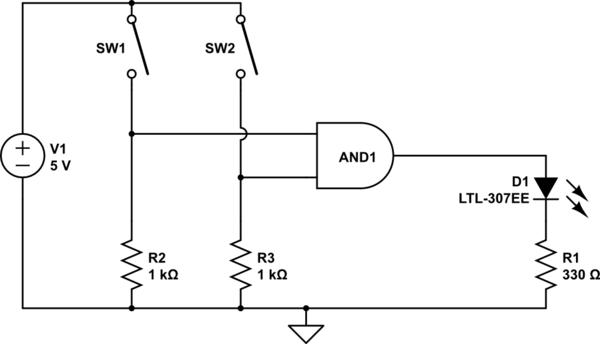
The AND output will be high when both switches are closed. However, there is no assurance regarding the input levels when the switches are open, resulting in unpredictable outcomes. In an electronic circuit utilizing an AND gate, the operation is...

This is a simple hobby circuit for a remote-controlled toy car. The primary component utilized is the IR sensor circuit, which includes a TSOP IR receiver. This receiver allows the user to start and stop the DC motor of...
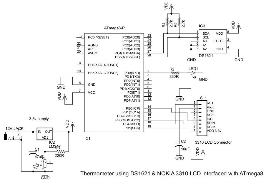
This document presents an application utilizing the Nokia 3310 LCD for designing a thermometer using the DS1621 temperature sensor IC. The DS1621 is an 8-pin sensor manufactured by Maxim. The circuit design involves integrating the DS1621 temperature sensor with a...
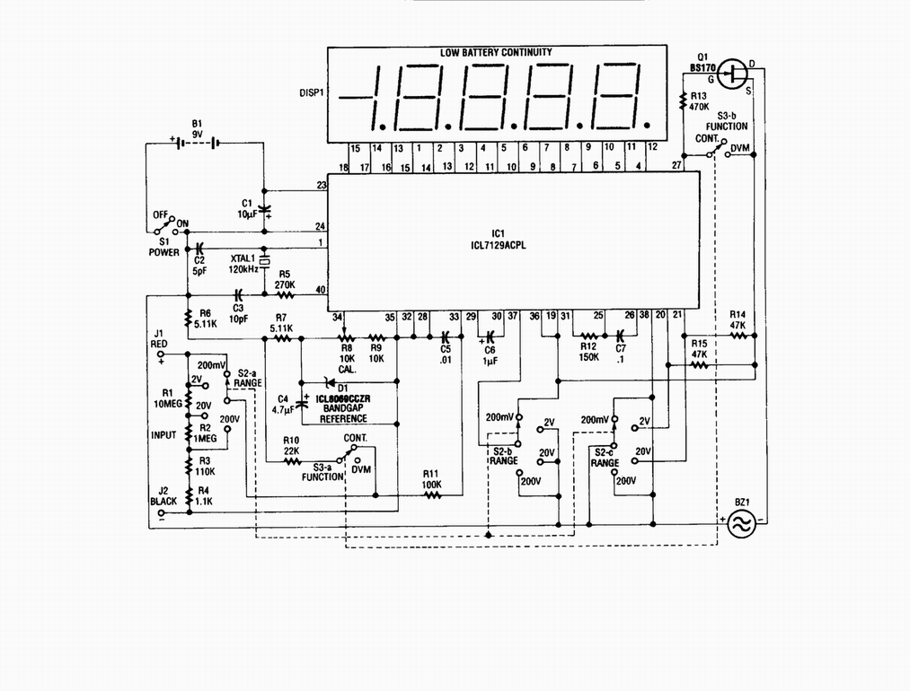
Single-chip digital voltmeter. This 4 1/2-digit DVM circuit is built around a Maxim ICL7129ACPL A/D converter and LCD driver. An ICL8069 CCZR 1.2-V band-gap reference diode is used for accuracy. The described circuit is a single-chip digital voltmeter (DVM) utilizing...
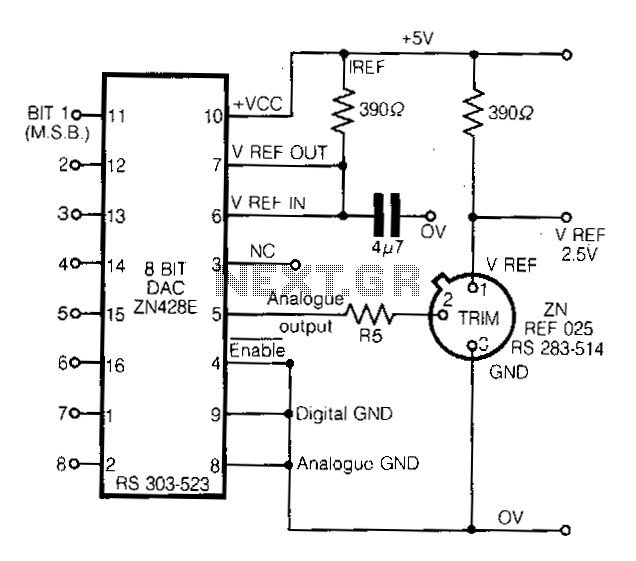
This circuit demonstrates a straightforward approach to achieving a voltage reference that can be adjusted using an 8-bit Digital-to-Analog Converter (DAC) equipped with an integrated voltage reference. The analog output from the DAC controls the trim pin of the...