
digital remote thermometer

The circuit described is a frequency measurement and display system that utilizes a combination of analog and digital components to process and present data derived from the mains supply. The initial stage involves the isolation of the mains frequency using capacitors C1 and C2 and inductor L1 to ensure safety and signal integrity. The amplification of the frequency pulses by transistor Q1 allows for a stronger signal that can be further processed without loss of information.
Diodes D1 and D2 serve a critical role in protecting the circuit from voltage spikes, ensuring that the input to the subsequent stages remains within safe limits. The filtering action provided by capacitor C5 smooths out any remaining noise in the signal, allowing for a cleaner square wave output from IC1B. This squaring process is essential for converting the analog frequency pulses into a digital format that can be counted.
The division of the frequency by 10 in IC2B is a crucial step that allows for a manageable output that can be displayed in a human-readable format. IC5, as the main counter, receives these pulses and is responsible for driving the display, which is facilitated by a multiplexing technique that allows for multiple digits to be shown without requiring separate control lines for each segment.
The time-base generator IC4 ensures that the counting process is synchronized and provides reset pulses to maintain the accuracy of the counting operation. The use of a 5Hz square wave derived from the mains frequency allows for a stable timing reference that is essential for accurate frequency measurement.
The multiplexing of the display cathodes through transistors Q2, Q3, and Q4 at a rate set by capacitor C7 allows for efficient use of the display segments while minimizing power consumption. The BCD-to-7 segment decoder IC6 translates the binary-coded decimal output from IC5 into the appropriate signals to drive the display segments, enabling the visual representation of the measured frequency.
Overall, this circuit effectively measures and displays frequency data, with the potential for various applications in monitoring and control systems where mains frequency is of interest. The design demonstrates a well-integrated approach to signal processing, amplification, and display technology within electronic systems.The frequency pulses coming from mains supply and safely insulated by C1, C2 & L1 are amplified by Q1; diodes D1 and D2 limiting peaks at its input. Pulses are filtered by C5, squared by IC1B, divided by 10 in IC2B and sent for the final count to the clock input of IC5.
IC4 is the time-base generator: it provides reset pulses for IC1B and IC5 and enables latches and gate-time of IC5 at 1Hz frequency. It is driven by a 5Hz square wave obtained from 50Hz mains frequency picked-up from T1 secondary, squared by IC1C and divided by 10 in IC2A. IC5 drives the displays` cathodes via Q2, Q3 & Q4 at a multiplexing rate frequency fixed by C7. It drives also the 3 displays` paralleled anodes via the BCD-to-7 segment decoder IC6. Summing up, input pulses from mains supply at, say, 2KHz frequency, are divided by 10 and displayed as 20.
0 °C. 🔗 External reference
Related Circuits
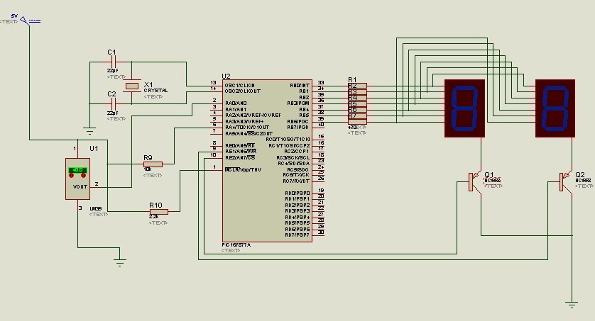
The circuit utilizes the LM35 temperature sensor to measure temperature in the range of 0 to 99 degrees Celsius and displays the readings using two seven-segment displays. It is designed to activate devices through the RC pins; for instance,...
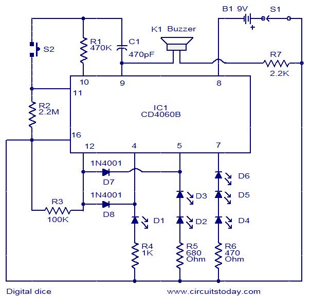
This is a simple and easy-to-construct digital dice circuit. The circuit is based on a single IC, CD4060B. The dice consists of six LEDs marked D1 to D6. The number of LEDs glowing indicates the numeral. The heart of...
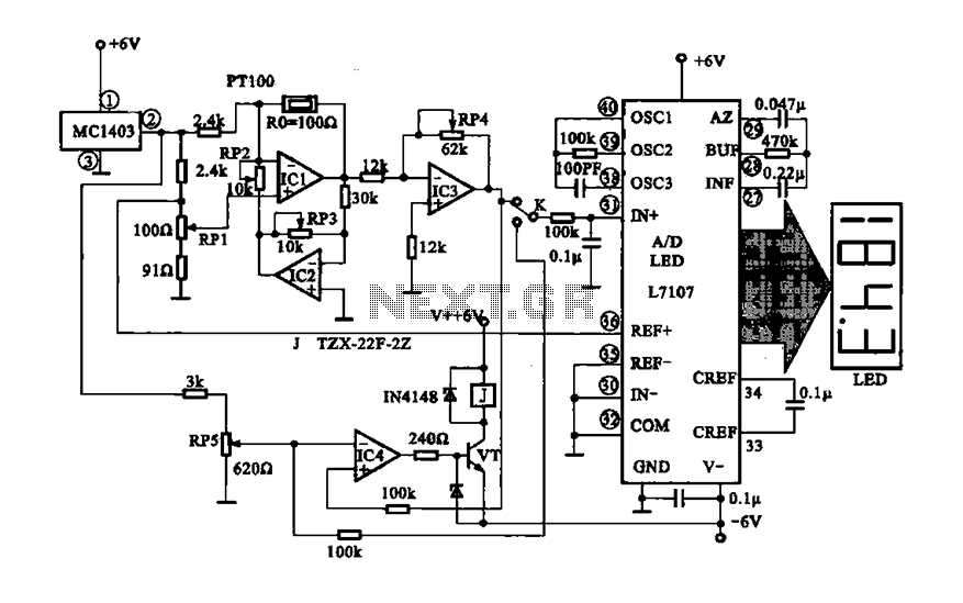
The digital display temperature detection circuit utilizes a precision digital display to indicate temperature readings. The circuit employs the MC1403, which outputs a reference voltage, with the potentiometer RP5 setting the reference value for the inverting terminal (a) of...
The circuit of an FM Tracking Transmitter Circuit or Remote Control Transmitter Circuit is explained using a 555 IC and 2N4392 transistors. The FM Tracking Transmitter Circuit utilizes a 555 timer integrated circuit (IC) configured in astable mode to generate...

A replacement remote control system for an electric garage door was constructed after the original remote failed multiple times. Although the old remote could have been repaired, it was 35 years old and not particularly enjoyable to use. The...
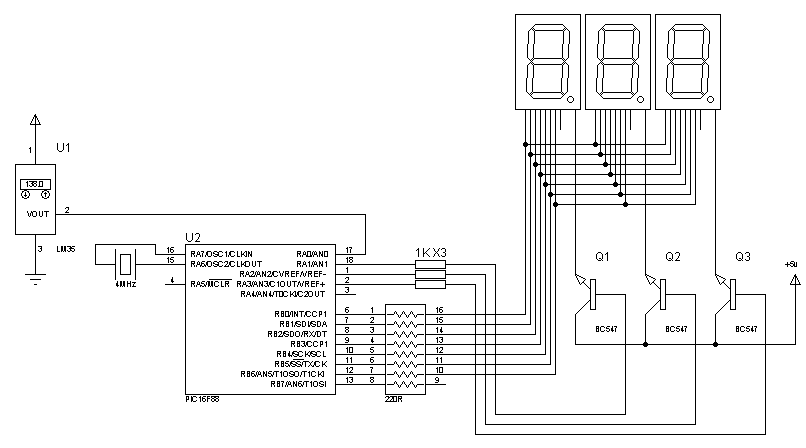
Assistance is needed to locate a schematic and code for a digital thermometer utilizing an LM35 temperature sensor and a 7-segment display, capable of measuring temperatures from 0 to 150.5 degrees Celsius. The required code must be included. The digital...
Warning: include(partials/cookie-banner.php): Failed to open stream: Permission denied in /var/www/html/nextgr/view-circuit.php on line 713
Warning: include(): Failed opening 'partials/cookie-banner.php' for inclusion (include_path='.:/usr/share/php') in /var/www/html/nextgr/view-circuit.php on line 713