
digital thermometer
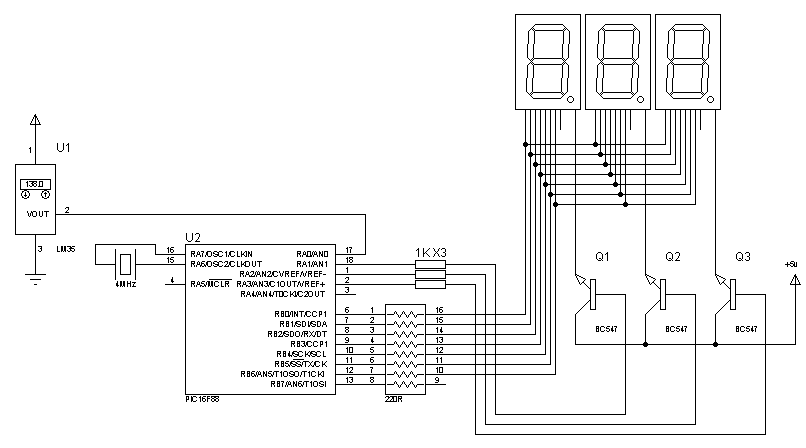
The digital thermometer circuit using an LM35 temperature sensor and a 7-segment display is a straightforward yet effective project suitable for various applications. The LM35 is a precision temperature sensor that provides an output voltage proportional to the temperature in degrees Celsius. It has a linear output of 10 mV/°C, making it easy to interface with microcontrollers.
The schematic consists of the following key components:
1. **LM35 Temperature Sensor**: This component is the core of the thermometer. It outputs a voltage that increases linearly with temperature. The output pin is connected to an analog input of a microcontroller (such as an Arduino) for temperature reading.
2. **Microcontroller**: A microcontroller is required to process the analog voltage from the LM35. It converts the voltage to a temperature reading using an Analog-to-Digital Converter (ADC). Popular choices include Arduino Uno or ATmega328 for their ease of use and extensive libraries.
3. **7-Segment Display**: This display consists of multiple LEDs arranged in a figure-eight pattern, allowing for the representation of numerical digits. To display the temperature, a common cathode or common anode 7-segment display can be utilized, depending on the design requirements.
4. **Resistors**: Current-limiting resistors are necessary for the 7-segment display to prevent excessive current from damaging the LEDs. The values of these resistors can typically be calculated based on the supply voltage and the forward voltage of the LEDs.
5. **Power Supply**: A suitable power supply is required to power the circuit. This could be a battery or a regulated DC power supply providing a voltage compatible with both the microcontroller and the 7-segment display.
The code for the microcontroller will involve reading the analog value from the LM35, converting it to a temperature reading, and then displaying that value on the 7-segment display. The code should include proper initialization of the ADC, reading the sensor value, and converting the voltage to temperature using the formula:
Temperature (°C) = (V_out / 10 mV).
The conversion will then be formatted to display on the 7-segment display, which may require multiplexing if multiple digits are used. The implementation can be achieved using libraries available for the selected microcontroller platform, simplifying the programming process.
This project serves as an excellent introduction to interfacing sensors with microcontrollers and displaying data, providing practical experience in electronics and programming.Can someone help me find a schematic and codes about a digital thermometer using a LM35 and 7 segment display(0 - 150.5 degree celcius)..the code must .. 🔗 External reference
Related Circuits
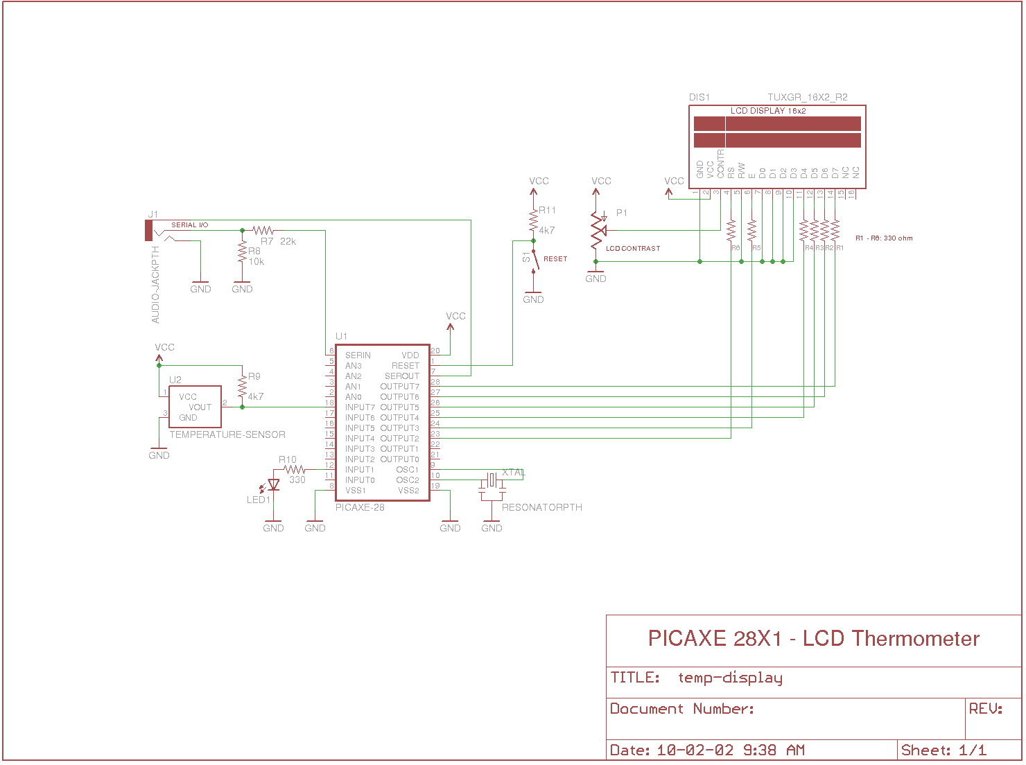
Measures the temperature using the DS18B20 temperature sensor, displays the reading on a 2x16 character LCD, sends the data to a serial terminal, and checks the temperature against predefined limits. The output is set high if the temperature is...
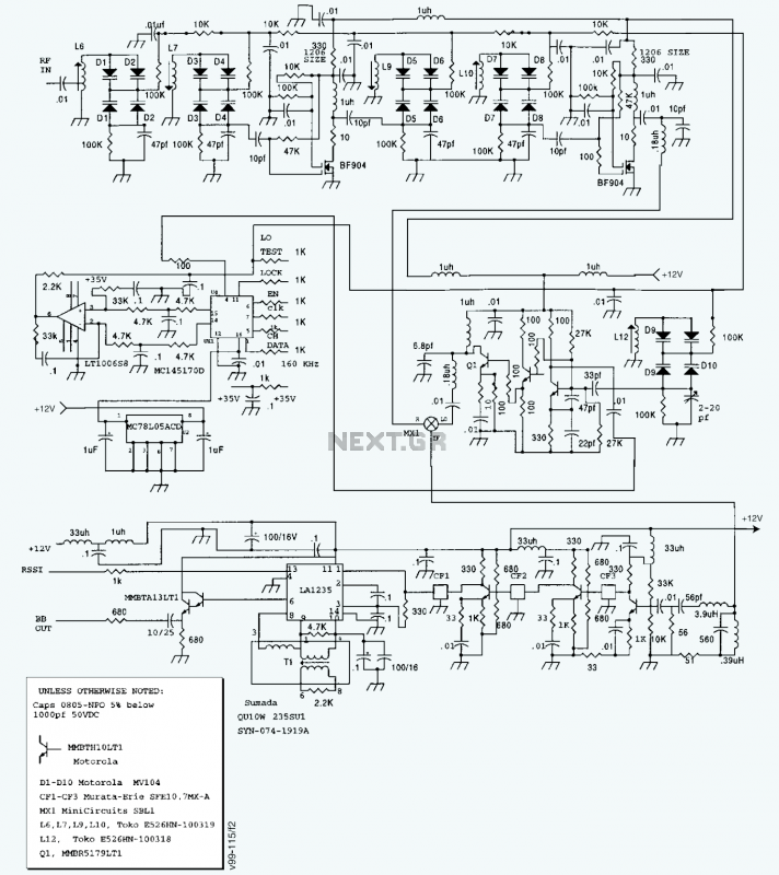
A block diagram and a schematic of the receiver are shown in Figures 2 and 3, respectively. In Figure 3, L6 and L7 are spaced 0.6 inch for a loss of about 0.5 dB. Q4 is the first RF...
The General Dynamic LED digital clock lacks a timekeeping function, but by adding a simple circuit, it can incorporate this feature. The integrated circuit (IC) includes a programmable mute function, which is inactive from 23:00 to 5:00 to avoid...
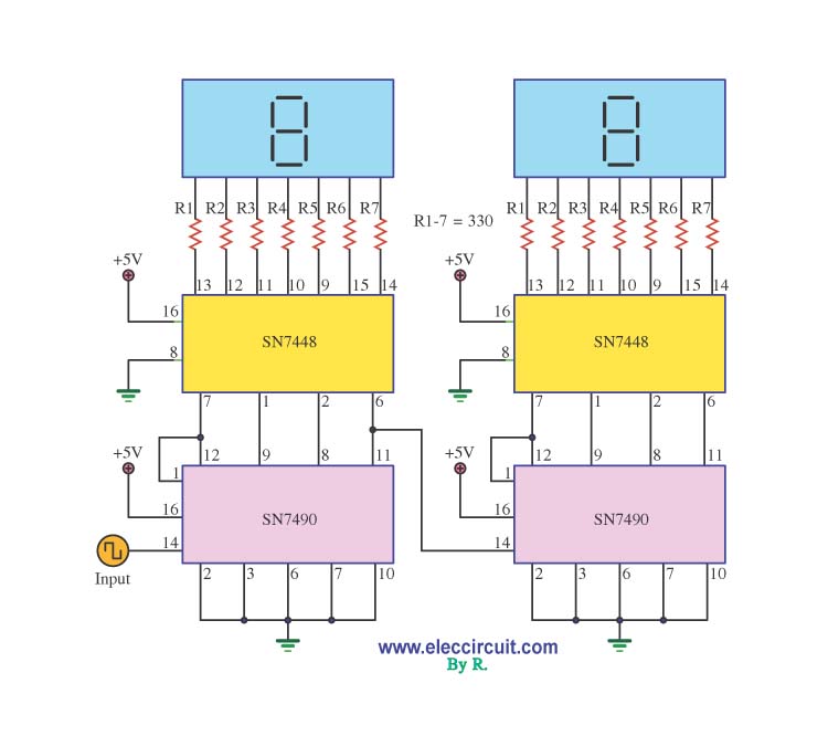
A decade counter circuit is an electronic circuit designed to perform a sequence of numerical calculations, allowing for either forward or backward counting. Forward counting refers to the circuit counting from smaller to larger numbers, while backward counting is...
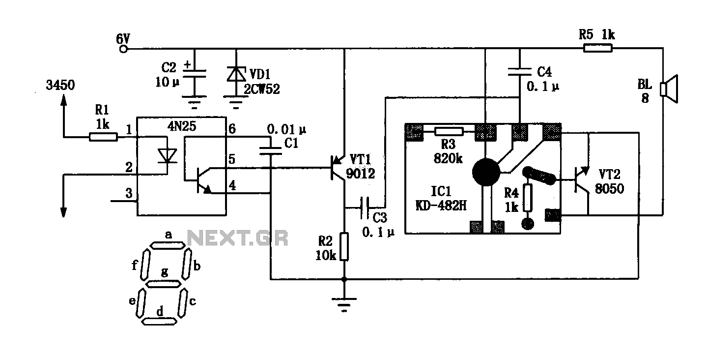
This digital thermometer indicates the temperature measured with an NTC using 7 LEDs. The circuit works using an opamp, the well-known 741, which amplifies the voltage difference between its plus and minus input. This amplification (sensitivity) can be set...
The circuit consists of two parts: The LM335 and its adjustment. The output of the LM335 is 10 millivolts per degree C, with 25 degrees C corresponding to 2.982 VDC. A reference circuit provides a zero reference voltage. It...