
Digital Thermometer

Figure 1 depicts the circuit diagram of the DigiThermo. The system utilizes the ATMEL 89C4051 CMOS Microcontroller, which features 4kB of code memory, 128 bytes of on-chip RAM, and 8-bit ports (Port1 and Port3). The analog-to-digital converter (A/D) is the HARRIS CA3162, a 3-digit digital voltmeter (DVM) that employs a dual-slope integrator, allowing for a sampling rate of 10Hz. The digital output from the A/D converter is sent to the microcontroller as a multiplexed four-bit Binary-Coded Decimal (BCD) signal, with the most significant digit (MSD) connected to P3.7 to indicate when the first digit is ready for reading. The integrating capacitor used in the circuit is a 330nF polyester capacitor.
Gain and zero adjustments for the A/D converter are facilitated by a 10k potentiometer connected to pin 13 and a 50k potentiometer connected to pins 8 and 9, respectively. The CA3162 has a true differential input, with pin 11 designated for the high signal and pin 10 for the low signal. The LM35D temperature sensor outputs a voltage of 10mV/°C, and since the A/D converter can provide readings from 0 to 1000mV with a 1mV resolution, it can effectively resolve temperature changes down to 0.1°C, although this does not guarantee absolute accuracy. A first-order low-pass filter is implemented using a 100k resistor and a 0.02µF capacitor as part of the front-end hardware filtering.
The 16x1 line LCD is interfaced in 4-bit mode to Port1 (P1.4-P1.7), with control signals RS and E connected to P3.4 and P3.5, respectively. The circuit is powered by a +5V supply derived from a 78L05 voltage regulator in a TO-92 package, utilizing an external +9V adapter.
The controlling program, named thermo.c, was developed in the C programming language and compiled using the Micro-C Compiler from Dunfield Development Systems. It operates under a TINY memory model, which is suitable for minimal hardware configurations, specifically in single-chip mode. The compiled hex file (thermo.hex) is intended for downloading via the Easy-Downloader V1.1. The program utilizes the 128-byte on-chip RAM for variable and stack storage.
The main program structure is designed to perform four key tasks: time management, data acquisition from the A/D converter, temperature display, and time display on the LCD. These tasks are executed at 100ms intervals, with the time function updating the time base and setting flags for elapsed time intervals. The putxin function shifts the converted digital data into a 10-word FIFO buffer, while the puttemp and puttime functions compute and display the average temperature and elapsed time, respectively, on the LCD.
Calibration of the A/D converter involves adjusting the zero offset by shorting the high and low input pins to ground and adjusting the gain using the potentiometers until the readings are accurate. For temperature calibration, it is recommended to use a standard thermometer with a higher precision than the LM35D. Calibration should be performed by placing both sensors in a temperature-controlled environment and recording their readings across a specified range. The correlation between the DigiThermo readings and the reference thermometer can be established using linear regression analysis, allowing for adjustments in the software to improve accuracy.A device designed for measuring time and temperature used in chemistry laboratory. The circuit employs a 89C4051, 20-pin CMOS Microcontroller with built-in 4kB code memory. Temperature was measured by LM35D, National Semiconductor Temperature sensor producing 10mV/°C. The CA3162, 3-digit DVM converts dc output provided by LM35D and sends BCD output to port1 (P1.0-P1.3). The program resided in code memory of 89C4051 was written in ‘C’ language, thermo.c. The program read BCD output from the A/D converter, performs digital filtering,10-point moving average, and sends the output reading to a 16x1 line LCD display.
A 10ms cputick was used as a timebase producing 1 s for time counting. The LCD displays time in 1 s and temperature in 0.1°C resolutions. Circuit Description Figure 1 depicts circuit diagram of the DigiThermo. The MCU is ATMEL 89C4051 CMOS Microcontroller having 4kB code memory, 128 bytes On-chip RAM and 8-bit Port1 and Port3. The A/D chip is HARRIS CA3162, 3-digit DVM. The A/D converter employs dual-slope integrator providing 10Hz sampling rate. Digital output sent to MCU is multiplex four bit BCD started from MSD, LSD and NSD respectively. The MSD signal was tied to P3.7 indicating first digit ready to be read. Integrating capacitor is a 330nF Polyester type. The 10k POT connected to pin13 is a gain adjustment and 50k POT to pin 8 and 9 is for zero adjustment.
The input of the converter is true differential pin 11 for HI and pin 10 LO signal. Temperature was measured by a precision solid-state sensor from National Semiconductor, LM35D. The output signal is 10mV/°C. Since the A/D converter is capable of providing 0-1000mV reading with 1mV resolution, thus the converter can resolve 0.1°C (not absolute accuracy). A 100k and 0.02uF forms a first order low-pass filter used to be front-end hardware filtering. The 16x1 line LCD is connected in 4-bit interfacing to P1.4-P1.7 with control signal RS and E to P3.4 and P3.5 respectively.
The +5V power supply uses a 78L05 TO92 case with external +9V adapter. Software The program thermo.c that control the Digithermo was written in ‘C’ language and was compiled by Micro-C Compiler from Dunfiled Development Systems. The memory model is TINY that use minimal hardware, i.e., single chip mode. The hex file of thermo.c suitable for downloading by Easy-Downloader V1.1 is thermo.hex. Variables and stack use the area of 128-byte on-chip RAM. Figure 2 depicts pseudo code of the control program. initialize timer0 init variable init LCD module put title message to LCD buffer do forever { do the following tasks every 100 ms; time(); /* update time base */ putxin(); /* put converted digital data to 10-word FIFO buffer */ puttemp(); /* put temperature reading to LCD */ puttime(); /* put second counter to LCD */ } Figure 2: Pseudo code of program thermo.c Main program separates tasks into four tasks, i.e., time( ), putxin( ), puttemp( ), and puttime( ).
These tasks were executed every 100ms. Time( ) set FLAG1 bit0, bit1 and bit2 when time has elapsed 100ms, 1st 10 count, and 1s respectively. Putxin( ) shifts a converted digital word to LSW of 10-word registers performing 10-point data moving.
Puttemp( ) computes average value of 10-sample and put to LCD buffer. Similarly puttime( ) writes variable count to LCD buffer. The device driver routines are readadc( ), read BCD from CA3162, LCDINI( ), initialize LCD, LCDWI( ), write LCD instruction, LCDWD( ), write ASCII code to LCD buffer, pulseE( ) generates Enable pulse, and delay(n), delay n milliseconds. As seen in the listing of thermo.c program, some function has embedded assembly code because of time critical requirements.
Variable ACC and temp are used to pass value to and from ‘C’ program. Please study in details writing style and variables usage. Zero and Gain of A/D Adjustment Before inserting LM35D, A/D needs a bit adjustment by adjusting ZERO which done by short pin HI and LO to GND. Then adjust 50k POT at pin 8 and 9 until temperature reading is 0. Put the reference voltage source 500mV to input of the A/D, adjust 10k POT until display shows 50.0. Calibrating Temperature Reading Although the LM35D is calibrated to Celsius, gain of the CA3162 may influence directly to accuracy of the reading.
It is good idea to make calibration with standard thermometer. Theoretically, the standard thermometer to be used as a reference should provide more precision at least one order. Suppose we want to calibrate our Digithermo with the designed precision of 0.1 °C, the standard reference should have precision at least 0.01 °C.
Not easy to find the reference right? Assume you may get one but having only 0.1 °C resolution for our calibration. First you need to have a temperature reservoir to put the reference thermometer and LM35D probe together. Ensure both are at the same temperature. Let the desired temperature range to be calibrated is 0-20.0 °C. Start records both readings from 0 to 20.0 by slowly warming the reservoir. To find the correlation between our instrument and the reference may easily done by using linear regression function in Excel spreadsheet.
Plot the reading of the Digithermo in X-axis and reference in Y-axis. Plot trend line using linear least square, we get the correlation equation as Y = 1.0053X - 0.0115. With this equation, reading from Digithermo is then easily be adjusted to the value read as read by reference thermometer. However the 1st version of DigiThermo does not provide such equation in the source program. Student should try insert the equation with some adaptation, since Micro-C math provides only integer mathematics.
🔗 External reference
Related Circuits
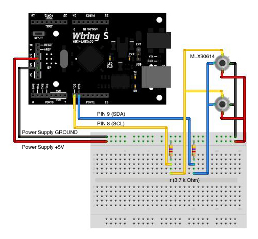
The MLX90614 is an infrared thermometer that allows for non-contact temperature measurement, providing average temperature readings for objects within its view range. Besides its primary function of measuring temperature, it can also be utilized for motion or presence detection....
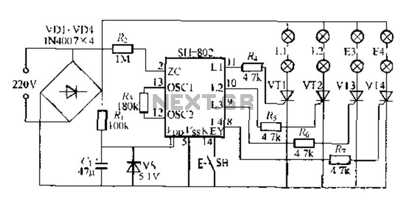
A digital integrated circuit simplifies the response process significantly. The diagram illustrates a circuit comprising four responder groups. The digital integrated circuit described serves as a crucial component in various electronic systems, primarily focusing on enhancing response efficiency. It comprises...
This is an electric thermometer circuit composed of the LM134. In the circuit, the voltage or current output by the LM134 is proportional to the thermodynamic temperature, which can be read on a 100 µA meter. The test temperature...
This Project Digital Calendar using Microcontroller is an advanced digital calendar, which displays the Date, Day, Month over the LED display. It has an 8 bit Microcontroller which runs on the Program embedded on its ROM. Separate LEDs are...
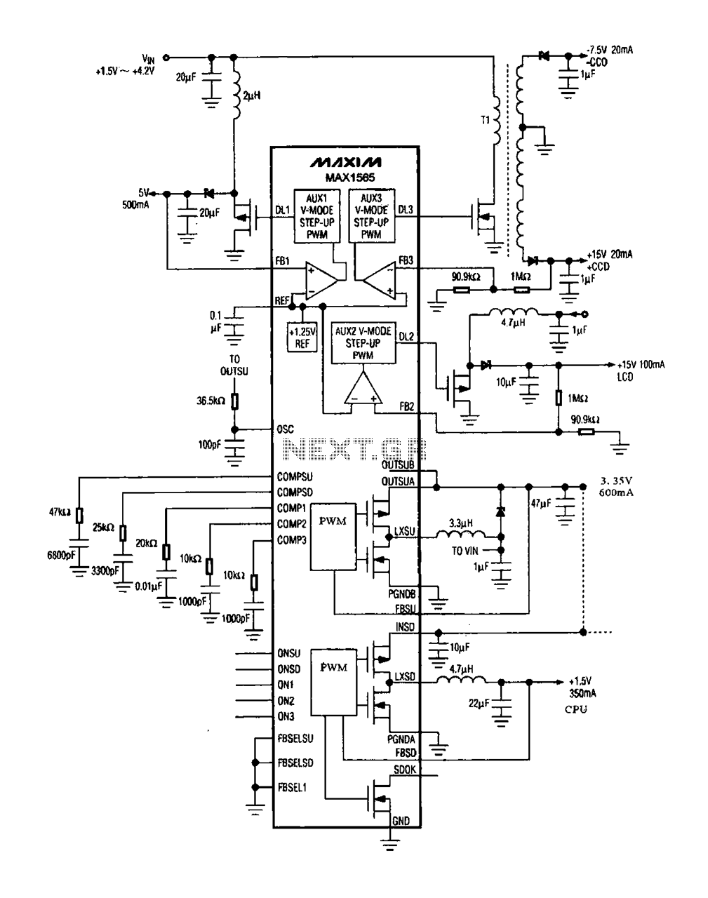
The digital camera power supply utilizes the MAX1565 chip, which features a five-channel power supply configuration. The chip generates various signal widths and control circuits tailored to meet the DC voltage and current requirements of the digital camera. The...
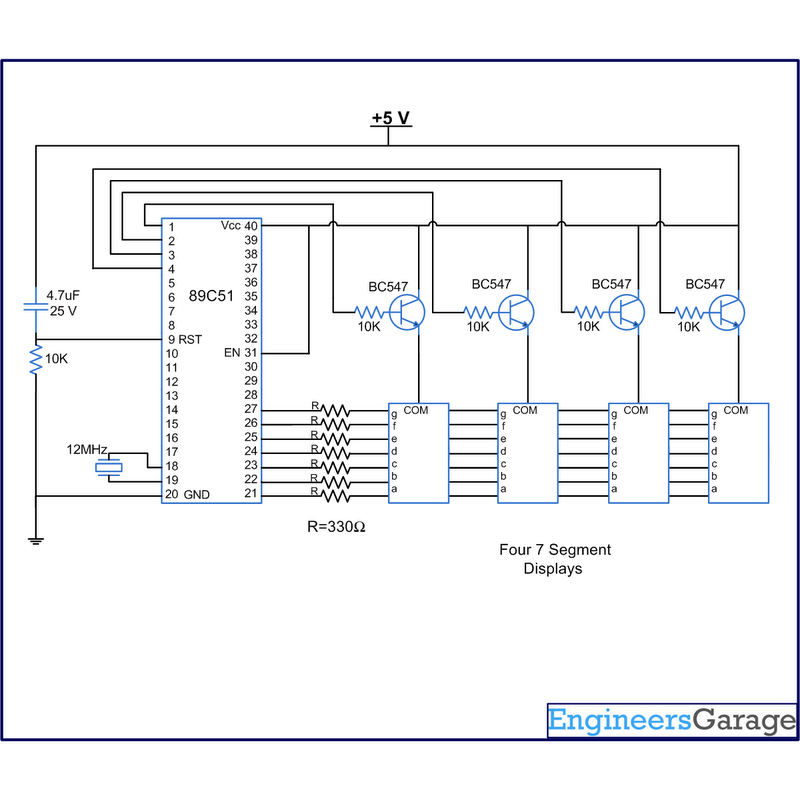
A digital clock displays time in a digital format. The circuit outlined here shows the time with double-digit minutes and two digits for seconds across four seven-segment displays. The segments of the displays are interconnected with the 8051 microcontroller...
Warning: include(partials/cookie-banner.php): Failed to open stream: Permission denied in /var/www/html/nextgr/view-circuit.php on line 713
Warning: include(): Failed opening 'partials/cookie-banner.php' for inclusion (include_path='.:/usr/share/php') in /var/www/html/nextgr/view-circuit.php on line 713