
Digital Volume Control
The described digital volume control circuit utilizes a microcontroller or a dedicated volume control IC (U1) from Dallas Semiconductor, which is designed to manage audio levels without the mechanical wear associated with traditional potentiometers. This circuit typically employs two momentary push-button switches, labeled S1 and S2, to increment or decrement the audio volume level.
The operation of the circuit begins when the user presses the UP button (S1) to increase the volume. This action sends a signal to the microcontroller, which processes the input and adjusts the volume accordingly. Conversely, pressing the DOWN button (S2) decreases the volume. The seamless integration of these buttons allows for a user-friendly interface, enhancing the overall experience of the audio system.
Power supply considerations are crucial for the performance of the circuit. A dual polarity power supply, providing both positive and negative voltages (typically ±5V), is recommended. This voltage range helps eliminate clipping issues that may arise when the audio signal exceeds the operational limits of the circuit components. It is essential to consult the specific datasheet for U1 to determine the correct pin configuration for power supply connections, ensuring reliable operation.
The input signal to the volume control circuit must remain above -0.2 volts to prevent distortion or loss of audio quality. This threshold ensures that the audio signal remains within acceptable limits for processing by the digital volume control.
Overall, this digital volume control circuit presents an innovative solution for audio applications, combining reliability, low noise operation, and ease of use, making it an excellent addition to any home audio project.This digital volume control has no pot to wear out and introduces almost no noise in the circuit. Instead, the volume is controlled by pressing UP and DOWN buttons. This simple circuit would be a great touch to any home audio project. Using a dual polariity power supply (+-5V works fine) will cure most clipping problems. You will have to check the data sheet for the correct pins to connect your voltages. The input signal should not fall below -0.2 volts. S1 turns the volume up, S2 turns it down. U1 is available from Dallas Semiconductor. 🔗 External reference
Related Circuits
A switch is an electrical component that can break an electrical circuit, interrupting the current or diverting it from one conductor to another. A switch may be directly manipulated by a human as a control signal to a system...
This ISP programmer can be utilized for in-system programming or as a standalone SPI programmer for Atmel ISP programmable devices. The programming interface is compatible with STK200 ISP programmer hardware, allowing users of STK200 to employ the software, which...
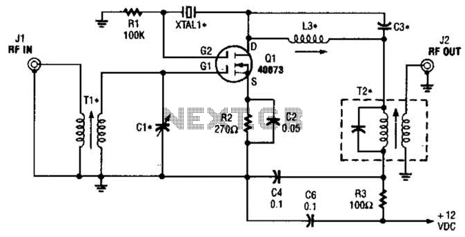
The second gate (G2) of a MOSFET can be utilized to integrate a crystal oscillator within the same stage as a frequency mixer. While this technique is common in tube technology, it is rarely implemented in dual-gate MOSFET circuits....
The integrated circuit input side contains an oscillating circuit, where the oscillation frequency is determined by the external components L1, C1, and the sensor's equivalent capacitance. The equivalent capacitance increases as the sensor is immersed in liquid. The oscillating...
Here's how you can make an electronic speed controller (ESC) for your remote control car, boat, or even an airplane using an old servo and some MOSFETs. Please note that this ESC has a very limited control range. Meaning...
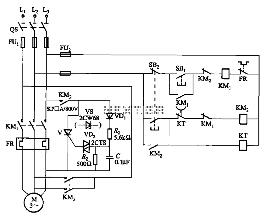
The circuit illustrated in Figure 3-148 eliminates the requirement for a step-down transformer by utilizing a thyristor for brake control in small capacity asynchronous motor braking applications. Upon shutdown, the contactor KM1 releases, while contactor KM2 engages the brake...