
Digital Wattmeter for 0-500MHz with PIC16F870
The wattmeter project described operates within a measurement range of 300 nW to 30 W across a frequency spectrum of 0-500 MHz. It utilizes a 50-ohm dummy load capable of handling up to 50 W for accurate power measurements. The output is displayed on a standard 2x16 character LCD, utilizing the HD44780 controller, which is a common choice for such applications due to its simplicity and reliability.
The core of the measurement system is the AD8307, an RF power detector that converts input power levels into a proportional DC voltage output. The device operates on a logarithmic scale, where an input power of 10 mW into a 50-ohm load corresponds to an output of 2.5 V DC. To ensure the AD8307 operates within its optimal range, a resistor ladder is used to scale down the input power appropriately. The ladder consists of five resistors: two 1.5 kΩ, one 1.8 kΩ, and two 100 Ω resistors, which together form a voltage divider to match the input characteristics of the AD8307.
The output from the AD8307 is then fed into a 12-bit analog-to-digital converter (ADC), which digitizes the analog voltage into a range of 0 to 4095. The digital output is subsequently processed by a PIC16F870 microcontroller, which retrieves the corresponding display text from a pre-calculated lookup table stored in a 32k EEPROM. This approach minimizes the need for complex calculations during runtime, allowing for faster processing and display updates.
Programming the EEPROM is facilitated through an RS232 interface, enabling users to upload the necessary data from a computer. This process simplifies the initial setup, requiring the user to ensure a switch (SW1) is closed during power-up to signal the microcontroller to enter programming mode. Once programmed, the wattmeter is ready for operation, providing an efficient and accurate means of measuring RF power across a wide frequency range.
In summary, this wattmeter design combines effective RF power measurement techniques with user-friendly features, making it a robust tool for various applications in electronics and RF engineering.This project will explain how I build my new wattmeter. This watt meter will be able to measure power from 300nW to 30W @ (0-500MHz). This wattmeter is based up on a dummy load of 50 ohm which can handle 50W. The measurement will be displayed in Watt on a 2x16 Char display. The unit is very accurate, fast and easy to build. This watt meter project is very similar to my last wattmeter project. The main reason I made a new project is becasue I needed a unit which could handle higher power than 1W. I found a 50 ohm dummy load which could take 50W of power. Of course I could use attenuates for my 1W meter, but I prefered to build a new unit. The new thing with this project is that it will only display the power in Watt on the LCD display. This means that I will not need so many EEPROM to store display data (more about this later). The input power is measured by the circuit AD8307. A resistor ladder will divide down the power to proper range for the AD8307 circuit. An A/D converter of 12 bit convert the analogue output from the AD8307 to a digital number. Since the AD is a12 bit A/D you will have 4096 combinations. The output values will be from 0 to 4095. Since the AD8307 gives a analogue voltage which represent the (dBm) of the input power, we need to recalculate the value to get the power in watt. The dBm is a logarithmic scale and that would include lot of math (floating point in the PIC processor) so I have chosen the easy way and used a lookup table instead.
It is memory bank containing all the display text. I have pre-calculated all the display text for each A/D value. The output values from the AD (0 to 4095) points to a direction in the memory where the actual display text value is stored. The text will be fetched and presented on the display. The advantage of using a memory map is that it will be easy to build, I can implement prefix in the text, it will be fast and it will work!
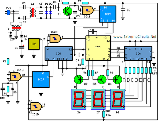
In reality I will use 1 EEPROM of 32k. The EEPROM is cheap but there is one tricky thing to do. The memory table must be programmed into the EEPROM before it can be used. You simply connect a RS232 cable to a computer and use a program I will support you with. This program will handle everything, just start the program and go make yourself a cup of coffee. Every memory cell will take 10-20ms to burn so it will take 10-15min. Directly connected over the input is a 50 ohm (dummy) resistor which can handle 50w. Then you will see 5 resistors forming a voltage divider to the AD8307. The resistors are 1.5k +1.5k +1.8k +100 + 100. How does all this work? Well, the AD8307 is actually a voltage RF measuring circuit. In the datasheet of AD8307, you will see that 10mW RF input into 50 ohm is equal to 10dBm and will give 2.5V DC out of the circuit. Now, which voltage will give 10mW into 50 ohm? P=U2/R => 0.01 = U2/50 => U = 0.707V. Now, we know that 0.707V RF input will give 2.5V DC out of the circuit. I my schematic I have used a 100 ohm resistor over (+In and -In). We must not forget that the circuit iself has an input resistance of 1.1k ohm. So let's start calculating backwards and have some brain exercise...*lol* 1.1k//100 = 91.66 ohm. Let us now calculate the input resistance which the RF signal will see. Rin =50//(1.5k+1.5k+1.8k+100+91.66) = 49.50 ohm...pretty good match. If I put 30W into this system the voltage over the input would be: P=U2/R => 30 = U2/49.50 => 38.54 V To get a 2.5V DC out of the AD7307 (which was equal to 0.707V RF-in), We have to scale down the 38.54V to the 0.707V.
38.54/0.707 = 54.5 times. Since the Rin was 91.66 ohm we can calculate the scaling resistor of the ladder. Scale = (Rladder + 91.66)/91.66 = > Rladder should be 4904 ohm. In my case I use 1.5k + 1.5k + 1.8k + 100 = 4900 ohm....pretty good match. Puhhhh, that was some bori...basic math, lets move on to more fun stuff :-) The output signal from the AD8307 goes to an A/D circuit which are controlled by the PIC16F870. To the PIC is an EEPROM connected. This EEPROM will contain the look-up table for the display. The display in this project is a basic 2 line and 16 char LCD display based on a HD44780 controller circuit (most common).
As I told you earlier, the EEPROM must be programmed from a computer to make this unit work properly. The connection to a computer is done by a RS232 wire. The programming procedure is very simple: Start the main program in the computer and connect the RS232 wire to the wattmeter.
Before you turn on the power of the wattmeter you should make sure that the switch SW1 is closed. This will indicate the PIC that it should program the EEPROM. Now turn on the power and hit the button of the software called "Program EEPROM". Everything will now be automatically. When program is finished you should turn off the power and remove SW1. The unit is now ready to be used. 🔗 External reference
Related Circuits
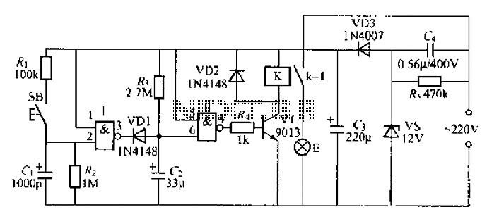
A 2-input NAND gate integrated circuit is used in the fabrication of a digital delay lamp circuit. This circuit is energized by a simple capacitive voltage rectifier, which operates by crossing the half line. The output terminal indicates the...
This circuit is designed for precise measurement of temperature in degrees Celsius. It features a transmitter section that converts the output voltage from a temperature sensor, which is proportional to the temperature being measured, into frequency. The resulting frequency...
Digital filters are powerful yet user-friendly, contributing to the popularity of digital signal processing (DSP). For example, a low-pass filter with a cutoff frequency of 1 kHz can be implemented in analog electronics. This method is often utilized for...
Measuring inductance is important for creating hand-made inductors, particularly when engaging in do-it-yourself (DIY) coil winding. An inductance meter adapter can facilitate this process. An inductance meter adapter is a vital tool for accurately measuring the inductance of coils and...

The circuit described is a crystal oscillation circuit using a CM OS inverting configuration, designed to ensure accurate operation. It employs a BCD counter (IC2) capable of achieving a maximum oscillation frequency of 2 MHz, which is 100 times...
This DIY digital thermometer circuit can measure temperatures up to 150 °C with an accuracy of ±1 °C. The temperature is displayed on a 1V full-scale deflection (FSD) moving-coil voltmeter or digital voltmeter. An operational amplifier IC 741 (IC3)...
Warning: include(partials/cookie-banner.php): Failed to open stream: Permission denied in /var/www/html/nextgr/view-circuit.php on line 713
Warning: include(): Failed opening 'partials/cookie-banner.php' for inclusion (include_path='.:/usr/share/php') in /var/www/html/nextgr/view-circuit.php on line 713