
Digitaxly tuned low power active filter
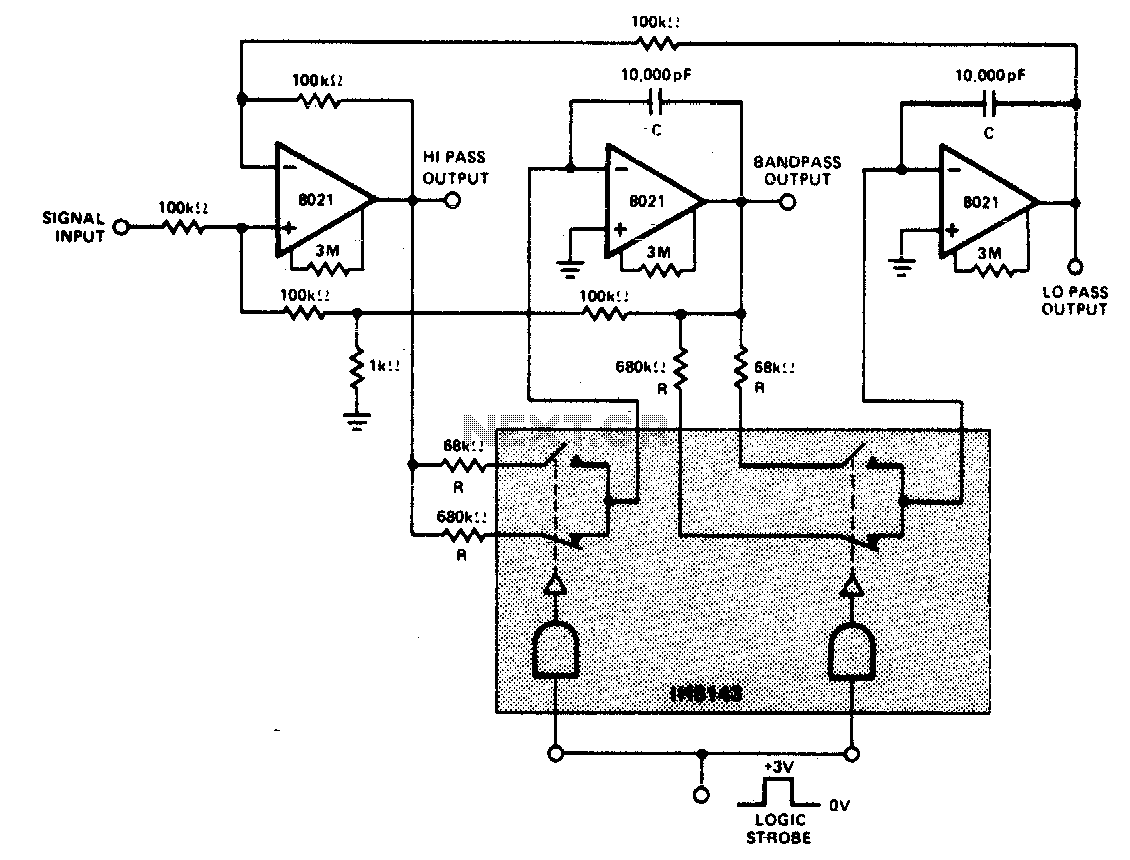
This circuit functions as a versatile filter, capable of producing three distinct output types: low-pass, bandpass, and high-pass. The constant gain characteristic ensures that the output amplitude remains stable across the frequency spectrum, while the constant Q factor allows for a narrow bandwidth around the center frequency, enhancing selectivity.
The filter's design is centered around the use of operational amplifiers (op-amps) configured in feedback loops, which help achieve the desired gain and Q factor. The choice of component values is critical; resistors and capacitors are carefully selected to set the center frequencies at 235 Hz and 23 Hz for high and low logic inputs, respectively. The Q factor of 100 indicates a high degree of resonance at the center frequency, making the filter particularly effective for applications requiring precise frequency selection.
In practical applications, this type of filter can be employed in audio processing, telecommunications, and signal conditioning, where simultaneous access to different frequency bands is required. The low-pass output allows for the passage of signals below a certain frequency, the bandpass output isolates a specific frequency band, and the high-pass output enables the transmission of signals above a designated frequency.
The implementation of this filter requires careful consideration of power supply requirements, as well as layout and grounding techniques to minimize noise and distortion. Properly designed, this filter can significantly enhance signal integrity in various electronic systems.Constant gain, constant Q, variable frequency filter which provides simultaneous low-pass, bandpass, and high-pass outputs With the component values shown, center frequency will be 235 Hz and 23 Hz for high and low logic inputs respectively, Q = 100, and gain = 100. 🔗 External reference
Related Circuits
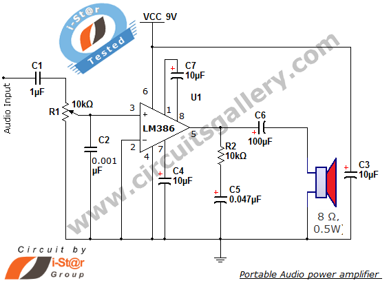
The i-St@r presents a simple mini audio amplifier circuit schematic utilizing the LM386 low voltage audio power amplifier IC. This circuit is designed to power medium-sized speakers from a music player that typically drives only earphones (LM386 headphone). The...
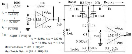
This topic continues from the more general Passive Tone Control circuit, which begins using only passive filters. This circuit follows the previous design, although the component values are different and in an alternate configuration. An audio tone control combines...

This is a 12V 100mA transformerless power supply designed for low current applications. C1 is an X-rated AC capacitor that reduces peak AC voltage. D1-D4 are diodes that rectify AC to DC, and C2 is used to filter out...
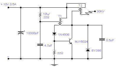
Easy to build, this high voltage generator is capable of generating up to 50KV but the breakdown voltage of the coil limits the voltage to a value somewhat lower. T2 is the ignition coil of a car and also...
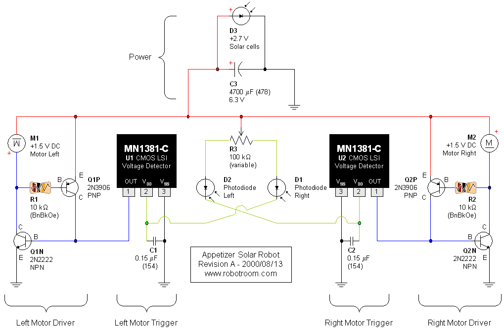
A light-seeking solar-powered tiny robot based on a BEAM design. The article includes pictures, links, a video, and a schematic. The described robot employs a BEAM (Biology, Electronics, Aesthetics, and Mechanics) design philosophy, which emphasizes simple, efficient, and often analog...
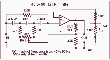
On this page three adjustable notch filters configurations are shown. They can be used in your small pre-amp or amplifier project to filter out any HUM at 50 Hz (European) or 60Hz. By substituting the capacitors values in the...
Warning: include(partials/cookie-banner.php): Failed to open stream: Permission denied in /var/www/html/nextgr/view-circuit.php on line 713
Warning: include(): Failed opening 'partials/cookie-banner.php' for inclusion (include_path='.:/usr/share/php') in /var/www/html/nextgr/view-circuit.php on line 713