
Diode digital thermometer circuit
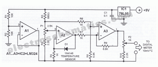
The digital thermometer circuit leverages the characteristics of the 1N4148 diode, which exhibits a predictable voltage drop that varies with temperature. As the temperature changes, the forward voltage drop across the diode decreases at a rate of approximately 2 mV for every degree Celsius increase in temperature. This property allows the diode to function effectively as a temperature sensor.
In the schematic, the 1N4148 diode is connected in a forward-biased configuration. The output voltage from the diode is fed into an analog-to-digital converter (ADC), which translates the analog voltage signal into a digital format suitable for further processing. The ADC is typically integrated into a microcontroller or a dedicated digital thermometer chip.
The circuit may also include additional components such as resistors and capacitors to stabilize the readings and filter out noise. A reference voltage source is often employed to calibrate the output of the ADC, ensuring accurate temperature readings. The microcontroller processes the digital signals received from the ADC and can display the temperature on an LCD or LED screen, or transmit the data wirelessly for remote monitoring.
Overall, this digital thermometer circuit is a cost-effective and straightforward solution for temperature measurement, leveraging the well-documented properties of the 1N4148 diode.This digital thermometer circuit diagram uses a common 1N4148 diode as the temperature sensor. The temperature coefficient of the diode, -2 mV / 0C is expl. 🔗 External reference
Related Circuits
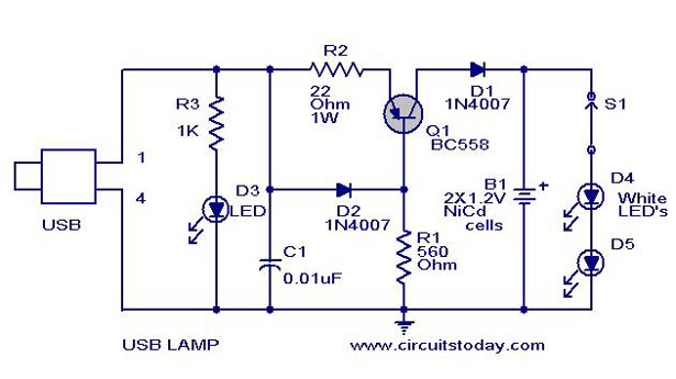
A simple USB LED lamp circuit utilizing a 5-volt power supply sourced from a USB port, designed to illuminate a desktop or laptop computer during power outages. The USB LED lamp circuit operates by converting the 5-volt DC power provided...

A fan regulator circuit that can also function as a simple lamp dimmer circuit. This fan speed regulator or light dimmer operates based on power control using a triac. The fan regulator circuit is designed to control the speed of...

The circuit illustrated is designed to generate up to 5 watts of RF output in the 40-meter (7 MHz) amateur band. The coils depicted are wound on toroidal cores from Armdon Associates Inc., with part numbers provided in the...
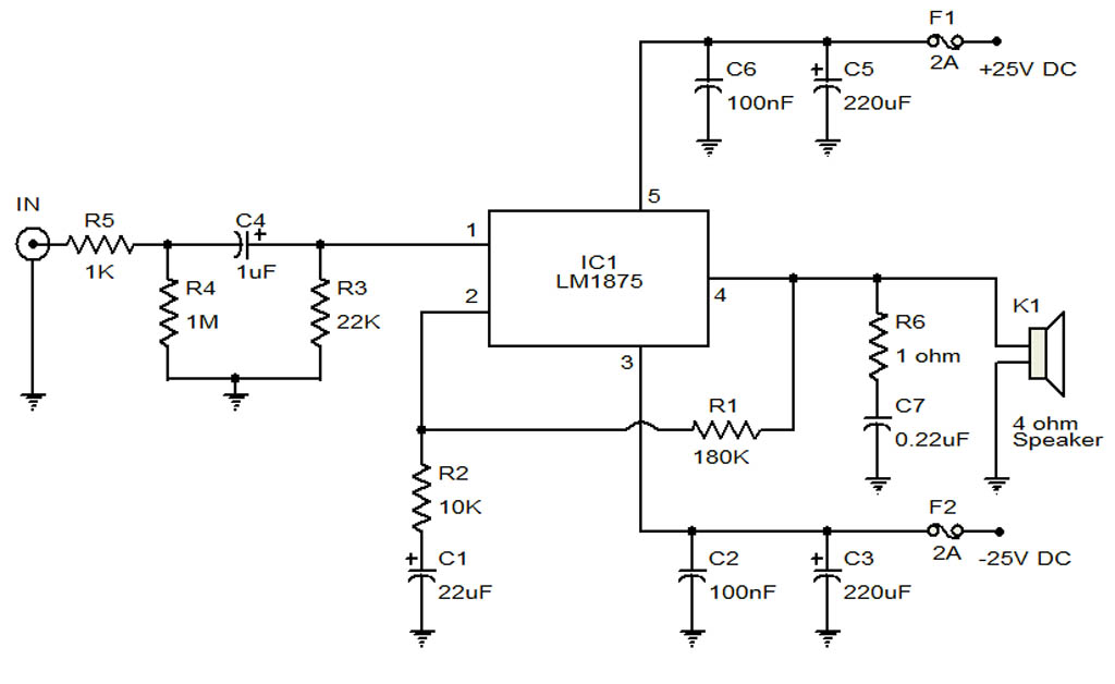
The circuit illustrates a 20-Watt audio amplifier diagram based on the LM1875 integrated circuit (IC). It is designed for use in automotive applications and provides an output power of 20 Watts. The 20-Watt audio amplifier circuit utilizing the LM1875 IC...
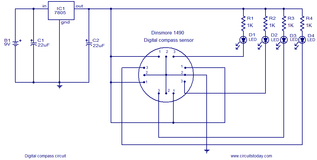
The following circuit illustrates a Digital Compass Circuit. This circuit is based on the 7805 IC. Features include a simple and accurate electronic compass. The Digital Compass Circuit utilizes the 7805 voltage regulator to provide a stable 5V supply necessary...
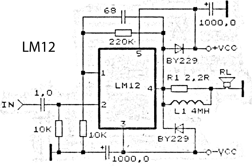
This is an amplifier circuit utilizing the LM12 integrated circuit as the primary amplifier. The amplifier delivers a power output of 150 watts and operates with a load impedance of 4 ohms. It is classified as a high-output power...