
DIODE-SWITCHED SYNTHESISER
The MC145152-2 synthesizer can be programmed using DIP switches, a diode matrix, or EPROM look-up tables. However, it is now difficult to find, costing around US$30. Modern synthesizers require PIC processors for programming or must remain connected to a computer. Today's synthesizers are increasingly surface-mounted, making them less accessible for hobbyists. The desire is for a synthesizer that can be easily constructed using basic components. This project involves three standard CD4000 series CMOS chips, which are readily available. A basic CMOS synthesizer based on the CD4046B can function up to about 3.5 MHz, primarily for demonstration purposes. With improved filtering, it can be adapted for communication applications. The redesigned project will utilize easily obtainable CMOS components and incorporate dual modulus operation. The block diagram of a basic synthesizer includes an R-counter that generates the reference frequency; the MC145152-2 offers several options while this project will provide over 2000. The N-counter divides the output from the external voltage-controlled oscillator (VCO), and the difference between the N-counter output and the reference frequency produces an error signal to control the VCO. This CMOS synthesizer can achieve frequencies up to 4 MHz with the CD4046B chip, or approximately 30 MHz with an external VCO. For instance, with a reference frequency of 12.5 kHz, the desired frequency of 28.550 MHz would yield an N-count of 2284. Adjusting the program to 2285 would produce 28.5625 MHz. However, achieving a frequency of 145 MHz requires a prescaler due to the limitations of CMOS technology. A prescaler dividing by 32 necessitates a reference frequency of just over 390 Hz to maintain 12.5 kHz steps. The loop must also be heavily filtered, resulting in slower frequency changes. For example, a frequency of 28.550 MHz with a /32 prescaler would require a divide rate of 71.375, which is unfeasible. A dual modulus prescaler is necessary in this case. A fixed count division is termed a "fixed modulus" or "single modulus" counter. The MC145152-2 includes an A-counter, also known as a "Swallow counter," which works with the N-counter to adjust the prescaler’s divide rate. By alternating the prescaler between dividing by 33 and 32, the system can accurately achieve the desired 12.5 kHz steps. In the example of 28.550 MHz with a divide-by-64 prescaler and a 12.5 kHz reference, the N-count would be set to 71 (71 x 32 = 2272), and the 12 missing counts (2284 - 2272 = 12) would be assigned to the A-counter.
The project aims to create an accessible synthesizer using common components, focusing on the integration of the CD4000 series CMOS chips. The use of the CD4046B chip allows for effective frequency generation and modulation, while the additional A-counter enhances the flexibility of the frequency division process. The dual modulus prescaler design addresses the challenges of achieving higher frequencies beyond the capabilities of standard CMOS technology. By implementing these components in a straightforward manner, hobbyists can build a synthesizer that is both functional and educational, providing hands-on experience with electronic design principles. The overall architecture of the synthesizer is modular, allowing for easy adjustments and expansions, which is essential for experimentation and learning. The combination of standard CMOS chips ensures that the project remains cost-effective and accessible, encouraging innovation and creativity in synthesizer design.My particular favourite was the MC145152-2 that could be programmed with DIP switches, a diode matrix, or even a pair of EPROM look-up tables. But sadly, those days are over. The MC145152-2 costs about US$30, if you can find a supplier. Today we need to use PIC-processors to program modern synthesiser chips, or have them permanently connected to a computer.
Todays synthesisers are becoming more and more surface-mounted. Whatever happened to the bits that the hobbyist can actually use What I want is a synthesiser I can use. I want it accessible. I want to be able to use diodes or solder-blobs for programming. I want just "throw together" a slack-handfull of bits and make a working synthesiser, without having to take a course in yet another processor.
With these thoughts in mind I devised this project. It uses three different "bog-standard" CD4000 series CMOS chips, and not the hard-to-get ones, either. Have you ever tried to find a CD4059B recently A basic CMOS synthesiser is already on my homepages, based on the CD4046B.
It can work up to about 3. 5MHz, but it is only meant to demonstrate the synthesiser principles. If you add a bit more care to the filtering then there is no reason why you cannot use it for communications. But let us now re-design that project, using easy-to-get CMOS, and add dual modulus (swallow counter) operation.
Too good to be true Read on. Here is the block diagram of a basic synthesiser. The "R-counter" generates the reference frequency. In the MC145152-2 you have about 3 different options. In mine you will have over 2000 different options. The reference frequency can be interpreted as the channel-spacing of the final synthesiser. The "N-counter" divides the output of the external voltage-controlled oscillator (VCO). The output of the N-counter is compared with the reference frequency, and the different is the error signal that is used to control the VCO. My own CMOS synthesiser project is great up to 4MHz with the CD4046B chip, or with an external VCO up to about 30MHz, which is about the limit for CMOS.
If you had a reference frequency of 12. 5kHz, then divide the wanted frequency (eg. 28. 550MHz) by the reference frequency and you get the N-count. 28. 550MHz / 12. 5kHz = 2284. Change the program from 2284 to 2285 and you will get 28. 5625MHz. The basic problems arise when you want to build, say, a 145MHz synthesiser. 145MHz is out of the range of the CMOS, so a prescaler is used. But with a prescaler that divides by 32, you need to have a reference frequency of just over 390Hz if you want to get your 12. 5kHz steps. The loop also needs to be filtered so much that a change of frequency will take many seconds, instead of a couple of milli-seconds.
The previous example frequency of 28. 550MHz, when used with a /32 prescaler would need a divide rate of 71. 375 = not possible. What is needed is a "dual modulus" prescaler. Point of interest here: a divide with a fixed "count" is refered to as a "fixed modulus" or "single modulus" counter. Modulus is singular. It should become a "dual-moduli" counter in the plural form, but engineers are never very good at languages that cannot be expressed in "1"s and "0"s.
The MC145152-2 also has an "A-counter". The A-counter, sometimes called a "Swallow counter", works in tandem with the N-counter to change the divide-rate of a prescaler. By changing the prescaller to divide by 33 for a few cycles, then by 32, you can extend the count to fill in the gaps to get your 12.
5kHz steps again. To do this you need another counter - the A-counter. In the 28. 550MHz example, with a divide-by 64 prescaler and a 12. 5kHz reference, you would use an N-count set to 71 (71 x 32 = 2272), and put the missing 12 counts (2284 - 2272 = 12) into the new A-counter. Let us now take a closer look at the timing. But for th 🔗 External reference
Related Circuits
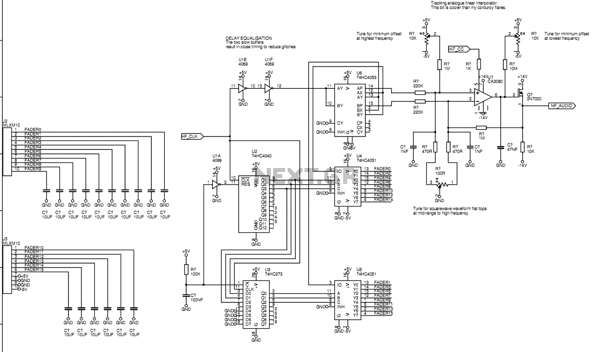
Originally I intended to have 32 faders. Once I tried fitting them on a veroboard, 32 seemed rather excessive so I have reduced to sixteen. This still allows generation of accurate eighth harmonic which compares well with the Hammond's...
Warning: include(partials/cookie-banner.php): Failed to open stream: Permission denied in /var/www/html/nextgr/view-circuit.php on line 713
Warning: include(): Failed opening 'partials/cookie-banner.php' for inclusion (include_path='.:/usr/share/php') in /var/www/html/nextgr/view-circuit.php on line 713