
Direction and speed control for series-wound motors
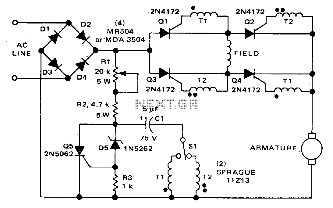
The circuit employs a bridge configuration of silicon controlled rectifiers (SCRs) Q1 to Q4, enabling efficient control over both the speed and direction of a series-wound DC motor. The series-wound motor is characterized by its field winding being connected in series with its armature winding, which allows for high torque at low speeds. The SCRs are activated in pairs, specifically in diagonal arrangements, which enables the motor to change its rotational direction based on the selected pair.
The operation begins with the user manipulating switch SI, which determines whether coupling transformer T1 or coupling transformer T2 is engaged with the pulsing circuit. This engagement is crucial as it dictates which diagonal pair of SCRs will be triggered. When SCRs Q2 and Q3 are activated, the field current flows in one direction, leading to a specific direction of rotation. Conversely, activating SCRs Q1 and Q4 reverses the field current, thus reversing the direction of rotation of the motor.
The armature current, which remains unidirectional, interacts with the reversed field current to produce the desired rotational effect. This characteristic of the series-wound DC motor makes it highly versatile for applications requiring variable speed and direction control.
The pulse circuit is integral to the operation, as it provides the necessary gate pulse to fire the SCRs. This pulse is generated from the energy stored in capacitor C1, which charges up when the circuit is idle and discharges to provide the required firing pulse when the switch is engaged. The timing and duration of the pulse can be adjusted to control the SCRs, thereby modulating the speed of the motor. The design ensures that the SCRs are only triggered when appropriate, preventing unwanted operation and ensuring safe, reliable motor control.
Overall, this circuit configuration exemplifies a robust method for controlling a series-wound DC motor's speed and direction, utilizing SCR technology for efficient power management and operational flexibility.The circuit shown here can be used to control the speed and direction of rotation of a series-wound dc motor. Silicon controlled rectifiers Q1-Q4, which are connected in a bridge arrangement, are triggered in diagonal pairs.
Which pair is turned on is controlled by switch SI since it connects either coupling transformer T1 or coupling transformer T2 to a pulsing circuit. The current in the field can be reversed by selecting either SCRs Q2 and Q3 for conduction, or SCRs Q1 and Q4 for conduction
Since the armature current is always in the same direction, the field current reverses in relation to the armature current, thus reversing the direction of rotation of the motor. A pulse circuit is used to drive the SCRs through either transformer T1 or T2. The pulse required to fire the SCR is obtained from the energy stored in capacitor Cl. 🔗 External reference
Related Circuits
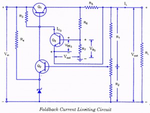
If the load resistance (RL) is reduced or the load terminals are accidentally shorted, a very large load current will flow, potentially damaging the pass transistor (Q1), diode, or other components. Fuse protection may not be sufficient, as the...
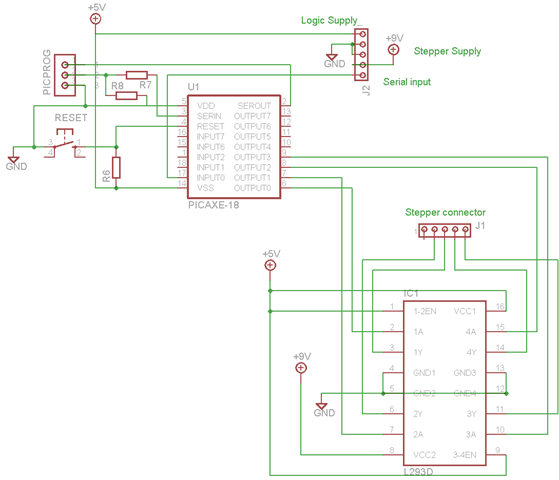
A schematic and program have been developed for operating a bipolar stepper motor through a serial interface, similar to the unipolar configuration. This is significant for the robot arm project, as two of the three stepper motors will be...

The generated alternating current (AC) at both ends of the voltage is adjusted after being rectified to supply the motor armature windings, allowing for speed adjustments of a 15W lamp. It is noteworthy that despite the freewheeling role of...

The first schematic page contains the primary content of the design, while the second page features simulation support circuitry. The primary design controls the accessory relays and indicators. It also drives the control loop and adjusts the throttle control...

The NE570 can be used to make a high performance compressor FTA, except that the rectifier is connected to the input. This makes gain inversely proportional to the input level so that a drop of 20 dB input level...

A quad 2-input NAND Schmitt trigger circuit can be designed using the MC14093 CMOS type IC, which serves as a simple pulse width modulation (PWM) controller electronic project. This PWM controller is straightforward and requires only a few external...
Warning: include(partials/cookie-banner.php): Failed to open stream: Permission denied in /var/www/html/nextgr/view-circuit.php on line 713
Warning: include(): Failed opening 'partials/cookie-banner.php' for inclusion (include_path='.:/usr/share/php') in /var/www/html/nextgr/view-circuit.php on line 713