
Discrete PWM Generator Circuit
PWM (Pulse Width Modulation) waveforms are essential in controlling the speed of DC motors due to their ability to vary the effective voltage supplied to the motor. The mark/space ratio, which determines the average power delivered to the motor, can be adjusted using either an analog voltage level or digital binary inputs. In applications where microcontrollers are not used, discrete logic components can efficiently generate PWM signals.
The circuit described can produce two PWM outputs from an 8-bit digital input. Each output can represent 15 different duty cycle values, allowing for fine control over motor speed. This is particularly useful in systems where precise motor control is necessary, such as robotics or automated machinery. The 8-bit input may originate from various sources, including a PC expansion board or a processor with limited PWM capabilities.
In the schematic, a binary input of 0000 results in both outputs being low, effectively stopping the motors. This feature simplifies the design, as an additional enable input is not required. The use of the HCF4060 integrated circuit as a clock generator allows synchronization of the PWM signals, ensuring that both channels operate in harmony.
The 74HC193 counter is critical for extending the circuit to produce two PWM signals. The integration of a flip-flop from the 74HC74 package provides additional functionality, enabling the second PWM channel. The design showcases an efficient use of components, requiring only four ICs to achieve dual PWM outputs, making it a compact solution for applications demanding dual motor control. Overall, this circuit exemplifies a practical approach to PWM signal generation using discrete logic components, suitable for a variety of electronic projects.PWM waveforms are commonly used to control the speed of DC motors. The mark/space ratio of the digital wave-form can be defined either by using an adjustable analogue voltage level (in the case of a NE555 based PWM generator) or digitally using binary values. Digitally derived PWM waveforms are most often produced by the timer/counter modules in m icrocontrollers but if you do not want to include a microcontroller in your circuit it`s also quite simple to generate the signals using discrete logic components. An extension of the circuit shown can produce two PWM wave-forms from an 8-bit digital input word. Each signal has 15 values. The 8-bit word can be produced for example from an expansion board fitted in a PC or from an 8-bit port of a processor which does not have built-in PWM capability or from a laptop`s printer port.
The mark/space ratio is only programmable up to 15/16 rather than 16/16; a binary input of 0000 produces a continuous low on both outputs turning both motors off. Similar circuits often employ a dedicated enable` input to turn the motors off but it is not necessary in this design.
The diagram shows the circuitry required to produce just one waveform. For the full two channel circuit it is necessary to use an additional 74HC193. The clock signal produced by the HCF4060 generator can be used to drive both channels and the free flip flop in the 74HC74 package can be used for the second channel (the corresponding pin numbers are shown in brackets). Altogether the entire two channel circuit can be built using just four ICs. 🔗 External reference
Related Circuits
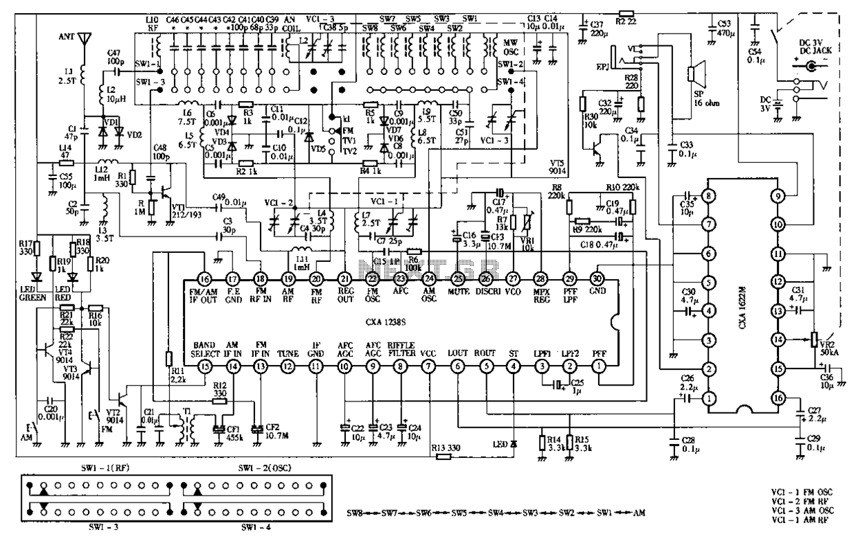
Desheng Rl212A 12-band FM, MW, SW, television sound stereo radio circuit diagram as follows: The Desheng Rl212A is a versatile radio circuit designed to operate across 12 different frequency bands, including FM (Frequency Modulation), MW (Medium Wave), and SW...
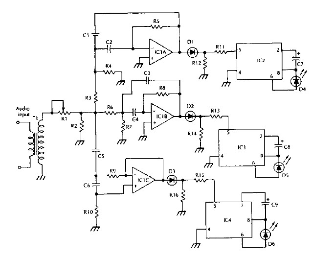
The LM 3909 LED flasher integrated circuit (IC) can be utilized to design various electronic projects. A circuit diagram illustrates the creation of a simple color organ using the LM3909 LED flasher IC. Three active filters process the audio...
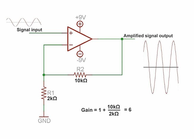
An amplifier is a device that increases the voltage in a circuit. The simplest type is an operational amplifier, and this video will demonstrate how these devices function and how to implement them in electronic applications. As an example,...
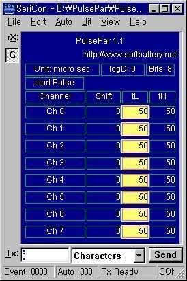
PulsePar turns a PC into a multi-channel pulse generator utilizing the parallel port. The period, duty and phase of each channel are adjustable so as to be used in PWM systems as well as in testing servo and stepper...
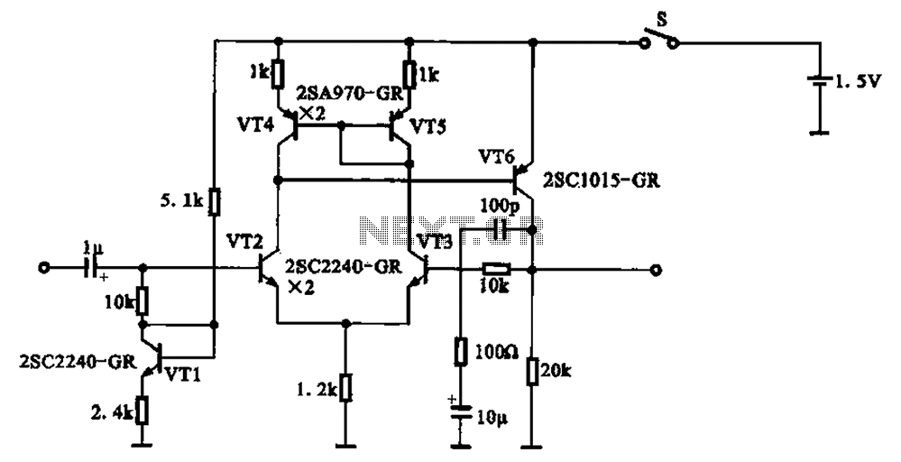
A 1.5V-powered microphone signal amplifying circuit is designed with a power supply for the microphone signal amplification. The circuit primarily consists of a differential amplifier formed by transistors VT2 and VT3. Additionally, VT6 functions as a common emitter voltage...
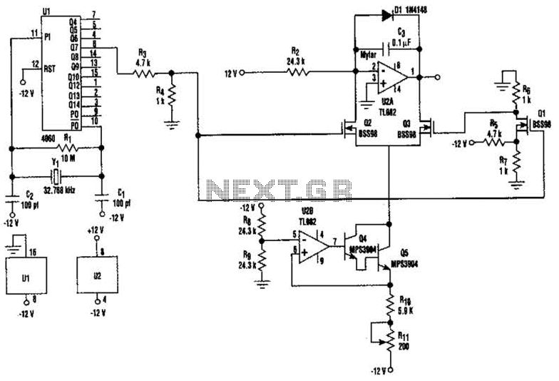
U2-a, U3, and R2 function as an integrator. Q2 and Q3 are alternately switched at 256 cycles. U2-b, Q4, Q5, and R8 through R11 form a constant current generator, with R11 configured to produce a symmetrical triangular waveform. The circuit...