
Divide-By-Odd-Number Counter
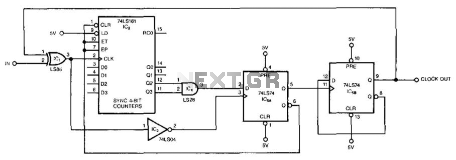
The described circuit functions as a frequency divider, utilizing a series of 74LS161 binary counters to achieve division by odd numbers ranging from 3 to 31. The fundamental operation relies on the selection of a specific value of n, which corresponds to the output of the counter, allowing for precise control over the division ratio. The circuit architecture includes n + 1 clock signals, where the additional clock signal is essential for synchronizing the operation of the counters.
The cascading of multiple 74LS161 counters facilitates the generation of higher divisors. Each counter can be configured to count up to a maximum of 15, thus enabling the division of the input signal by odd numbers effectively. The integration of IC5A and the counter forms the n + 1/2 configuration, which is crucial for the timing and control of the output signals.
Once the counter reaches the predetermined count, IC5A generates a clock pulse that triggers the clearing of the counter, effectively resetting its state and holding the output until the next cycle begins. The interaction between IC5A and IC5B introduces a phase-shifted clock signal through the XOR gate (IC1), which is instrumental in maintaining the correct timing for the subsequent counting operation.
The circuit's design has been validated at a frequency of 16 MHz; however, empirical analysis indicates that the maximum operational frequency is constrained between 7 MHz and 8 MHz. This limitation is due to the propagation delays and timing characteristics inherent in the components used, necessitating careful consideration when designing for higher frequency applications. The circuit's reliability and performance can be further enhanced by ensuring that all components are rated for the operational frequency and adequately managing signal integrity throughout the design. This circuit symmetrically divides an input by virtually any odd number. The circuit contains n + 1h clocks tw ice to achieve the desired divisor. By selecting the proper n, which is the decoded output of the 74LS161 counter, you can obtain divisors from 3 to 31. This circuit divides by 25; you can obtain higher divisors by cascading additional LS161 counters. The counter and IC5A form the n + ll-z counter. Once the counter reaches the decoded counts, n, IC5A ticks off an additional 1h clock, which clears the counter and puts it in hold.
Additionally, IC5A clocks IC5B, which changes the clock phasing through the XOR gate, IC1. The next edge of the input clocks IC5A, which reenables the counter to start counting for an additional n + 1/2 cycles. Although the circuit has been tested at 16 MHz, a worst-case timing analysis reveals that the maximum input frequency is between 7 and 8 MHz.
🔗 External reference
Related Circuits
An ordinary binary counter, such as the 7493, can be transformed into an up/down counter with mode control by adding XOR gates (7486) to the counter's outputs. The circuit counts up when the DN/UP line is low and counts...
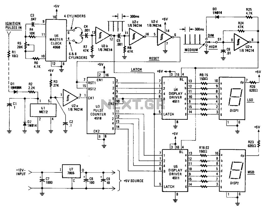
The Digi-Tach includes a master clock circuit (U6), latch and reset pulse generators (U2-b to U2-d), an input signal conditioner (U1, U2-a), a pulse counter (U3), display components and drivers (DIS1, DIS2, U4, and U5), as well as a...

The schematic for this project is visually acceptable, although it is not the most refined layout for a schematic. The basic flow progresses from left to right, starting with the state machine, followed by the 555 timers, then the...
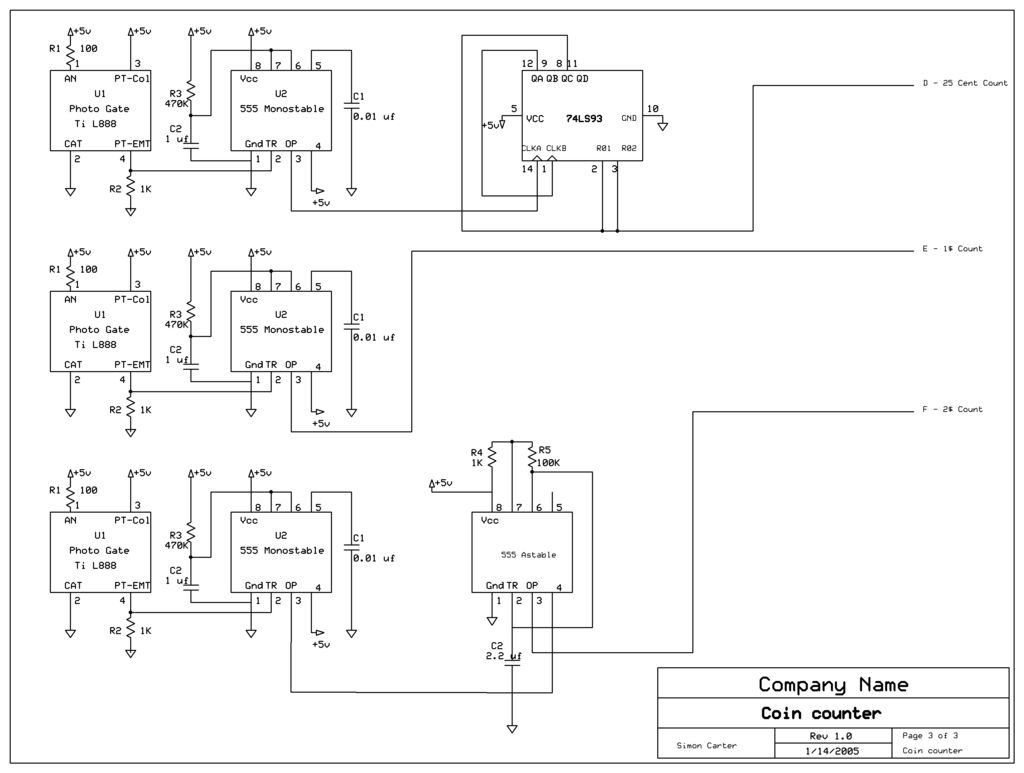
The next counter section operates similarly but is designed to count four quarters, single $1 coins (loonies), and single $2 coins (toonies). The circuit for the toonies is configured. The circuit for the counter section includes a digital counting mechanism...
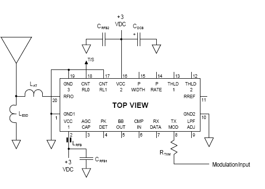
This system enables a Technical Surveillance Countermeasures (TSCM) specialist to briefly activate a Spectronics bugging device for a second or two to identify its presence, then deactivate it before the eavesdropper realizes that their device has been detected. A...
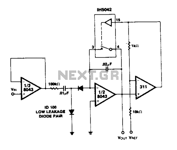
A simple circuit utilizing an LM311 as a level detector and a CMOS analog gate for capacitor discharge is presented. A notable feature of this counter type is the ease of changing the count, which only requires adjusting the...