
DIY Metal Detector Project

The CS209A IC serves as the primary signal processing unit in the metal detector circuit. It is designed to detect the presence of metallic objects by measuring changes in inductance caused by metal objects in proximity to the coil. The 100µH coil, which is a critical element of the system, acts as the sensor. When a metallic object is near the coil, the inductance changes, and the CS209A processes these changes to generate an output signal.
The circuit typically includes additional components such as resistors, capacitors, and a power supply, which are necessary for biasing the IC and filtering the output signal. The output can be connected to a speaker or LED to provide an audible or visual indication of metal detection.
For optimal performance, it is essential to calibrate the coil and adjust the sensitivity settings of the CS209A. The coil's placement and orientation can significantly affect detection range and accuracy. The circuit can be powered by a standard battery, making it suitable for portable applications.
Overall, this DIY metal detector circuit offers a practical and educational project for electronics enthusiasts, allowing for hands-on experience with inductive sensing and signal processing.The heart of this diy metal detector circuit is the CS209A IC. The metal detector is built with one 100µH coil that has 40 mm in diameter and is made.. 🔗 External reference
Related Circuits
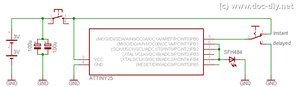
This site explains the process of constructing a low-cost DIY Canon RC-1 infrared remote control clone utilizing an AVR microcontroller. The project involves creating a remote control that mimics the functionality of the Canon RC-1, which is used for triggering...
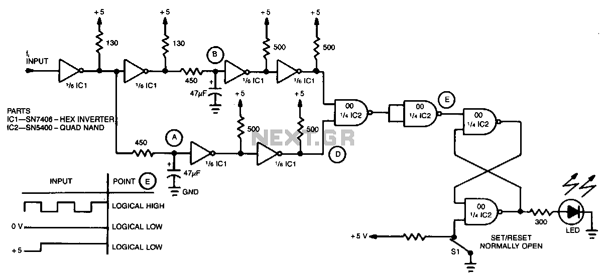
A simple inverter and NAND gate can be connected to create a highly compact and reliable digital frequency detector. This circuit is capable of detecting frequencies up to 3 MHz with a 50% duty cycle. When a frequency appears...
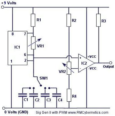
Construct a signal generator using readily available components. It should produce a square wave with variable frequency and adjustable pulse width. This device can be utilized for various applications, including DC motor speed regulation, dimming of lamps or LEDs,...
This circuit utilizes a complementary pair consisting of an npn metallic transistor T1 (BC109) and a pnp germanium transistor T2 (AC188) to detect heat. The circuit is designed to leverage the thermal sensitivity of the complementary transistor pair, where the...
In the absence of radiation, no current is drawn. At normal background radiation levels, the power consumption is extremely low. The instrument may be left on for several months without changing batteries. In this way, the detector is always...

The TDA2050 integrated circuit can be used to design a simple high-fidelity audio power amplifier, intended for use as a Class AB audio amplifier. Due to its high power capabilities, the TDA2050 audio power amplifier can deliver up to...