
diy-solid-state-relay.html
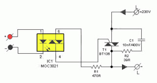
The primary advantage of a solid-state relay (SSR) over a traditional electromagnetic relay (EMR) is its reduced wear and tear, which enhances its longevity. The S201S01 model from Clear-Cut serves as an exemplary representation of this technology. The following is a circuit diagram for a DIY SSR project that features an isolated triac power controller. The switching output from one DC circuit can be connected to pin 1 of the opto-isolator (IC1) through a current-limiting resistor. Pin 2 of IC1 is grounded. When current flows through the internal LED of IC1, it triggers the internal diac, which subsequently provides a gate pulse to the triac (T1). This action turns on T1, enabling it to drive an AC mains-operated load through its output. The solid-state relay can be constructed on a single PCB and should be enclosed in a compact ABS housing. Proper holes must be drilled to mount four labeled input and output terminals. Since the switching is managed by triac T1, it is essential to avoid touching any components while the AC supply is connected.
The circuit design for the DIY solid-state relay (SSR) incorporates several key components that work together to facilitate efficient switching of AC loads. The opto-isolator (IC1) serves as the interface between the low-voltage control circuit and the high-voltage AC load, providing electrical isolation and protecting sensitive components from high voltages. The current-limiting resistor connected to pin 1 of IC1 is crucial for controlling the amount of current flowing through the internal LED, ensuring that it operates within safe limits.
Once the LED in the opto-isolator is energized, it activates the internal diac, which is a type of semiconductor device that switches on at a specific threshold voltage. This triggering action produces a gate pulse for the triac (T1), allowing it to conduct current and control the power delivered to the load. T1, being a bidirectional device, can handle AC loads effectively, making it suitable for applications requiring the switching of alternating current.
The PCB layout should be designed to minimize interference and ensure reliable operation. Adequate spacing between high-voltage and low-voltage traces is necessary to maintain safety and prevent accidental short circuits. The enclosure made from ABS plastic not only protects the circuit from physical damage but also provides insulation from electrical hazards. The labeled input and output terminals facilitate easy connection to the control circuit and the AC load, respectively.
Safety precautions must be observed during the assembly and operation of the SSR. It is critical to ensure that the AC supply is disconnected while assembling the circuit to prevent electric shock. Additionally, once the SSR is operational, users should avoid touching any part of the circuit to mitigate the risk of injury. Overall, this DIY solid-state relay project exemplifies a practical and efficient solution for controlling AC loads in various applications.Individual benefit of solid-state relay (SSR) above normal electro-magnetic relay (EMR) is its tear and wear emancipated surgical treatment. S201S01 from clear-cut is a superior paradigm. at this juncture is the circuit diagram of a DIY SSR project, which is all the rage truth an isolated triac power controller.
The switching output from one dc ci rcuit can exist connected to pin 1 of opto-isolator (IC1) through a right current limiting resistor. Pin 2 of IC1 is stuck. at what time current passes through the inner LED of IC1, internal diac is triggered and the diac provides the gate pulse to T1. at this moment T1 is fired to drive the ac mains operated load by the side of its output. past construction of the solid state relay on a joint pcb, enclose the undivided circuit appearing in a very unimportant ABS job.
Now drill correct holes to mount four labelled input and output terminals. Since switching is accomplished by triac T1, don`t converge the domestic parts while AC supply is plugged in. 🔗 External reference
Warning: include(partials/cookie-banner.php): Failed to open stream: Permission denied in /var/www/html/nextgr/view-circuit.php on line 713
Warning: include(): Failed opening 'partials/cookie-banner.php' for inclusion (include_path='.:/usr/share/php') in /var/www/html/nextgr/view-circuit.php on line 713