
DIY Welder Control Board
The circuit operates as a sophisticated welding control system, integrating digital and analog components to ensure precise voltage and current management during welding processes. The switching power supply controller forms the core of the design, utilizing a microcontroller to generate a reference voltage that facilitates real-time feedback and adjustments. The voltage sense amplifier, with its specific gain setting, ensures that the high voltage levels used in welding are accurately represented at a lower, manageable scale.
The summing amplifier plays a crucial role in comparing the desired welding voltage with the actual voltage, generating a differential signal that is essential for maintaining the desired performance. The comparator, driven by a triangle wave, modulates the output through PWM, allowing for dynamic adjustments in response to varying welding conditions. This PWM output is critical for controlling the MOSFETs in the output stage, which are selected for their efficiency in handling the high currents involved in welding applications.
In addition to the primary MIG welding function, the circuit is designed to adapt to Arc and TIG welding by incorporating a current sensing mechanism that modifies the output voltage in correlation with the current draw. This feature is particularly important in applications where maintaining a consistent arc is vital for quality welds. The variable gain setting allows for customization of the response characteristics, enabling the system to cater to different welding materials and techniques.
Optical isolation is employed throughout the design to ensure safety and reliability, protecting sensitive components from electrical noise and voltage spikes that can occur during welding operations. The inclusion of isolated power supplies further enhances the robustness of the system, ensuring stable operation under various conditions.
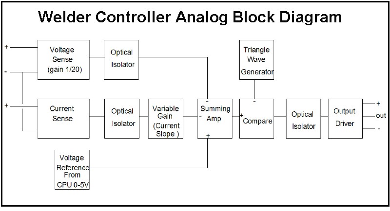
The user interface, consisting of front panel controls for voltage reference and variable gain, provides operators with intuitive access to adjust settings as needed. The simplified board version streamlines the design, reducing complexity while maintaining essential functionality, thereby making the system more accessible and cost-effective for users focused on alternator-driven welding applications. Overall, this circuit exemplifies an advanced approach to welding control, combining precision, efficiency, and adaptability.The first board was digitally controlled but the actual welding current is analog. This allows the board to operate real time without the need for the CPU to process the voltage/current. A block Diagram is shown below: It is basically a switching power supply controller. The CPU generates a 0 to 5 volt reference, that represents a 0-100V welding v oltage. The voltage sense amplifier has a gain of 1/20 so a 0-100V weld voltage will output a 0-5V signal. This is fed into a summing amp that generates a difference signal. this difference is fed to the comparator. The comparator is also fed a 20kHz triangle wave. The comparator will then output a PWM signal that varies with the difference in the desired voltage and the actual voltage. This signal is fed to the output driver to control the field current. The output stage uses MOSFETs for efficiency. For MIG welding, the above is all that is used. For Arc and TIG, the voltage should drop with current. The current sense input will also feed the current into the summing amplifier. A variable gain allows the current slope to be programmable. As an example, suppose the voltage is set to 40V. The current sense is programmed to a slope of 0. 3 volts per amp. At about 50 amps, the current sense will output the equivalent of 15 volts. The circuit will then drop the output voltage to 25V. At 100 amps it will drop to 10V. The inputs and outputs are optically isolated. This is for safety, protection from spikes and also allow the output to drive the field or saturation current off of any power source.
There is a small switching power supply that generates 3 isolated power supplies to power the input and output circuitry. The CPU can program the variable gain via an electronic potentiometer. The voltage reference is generated from a PWM output of the CPU that is fed through a low-pass filter to generate a 0-5V signal.
The CPU also monitors the voltage and current sense signals to output to the display. The "Simplified" board eliminates the isolators so the control circuits are tied to the - output if the alternator. This eliminates a lot of parts. The voltage reference and variable gain are controls on the front panel. It also is designed only to drive an alternator. 🔗 External reference
Related Circuits
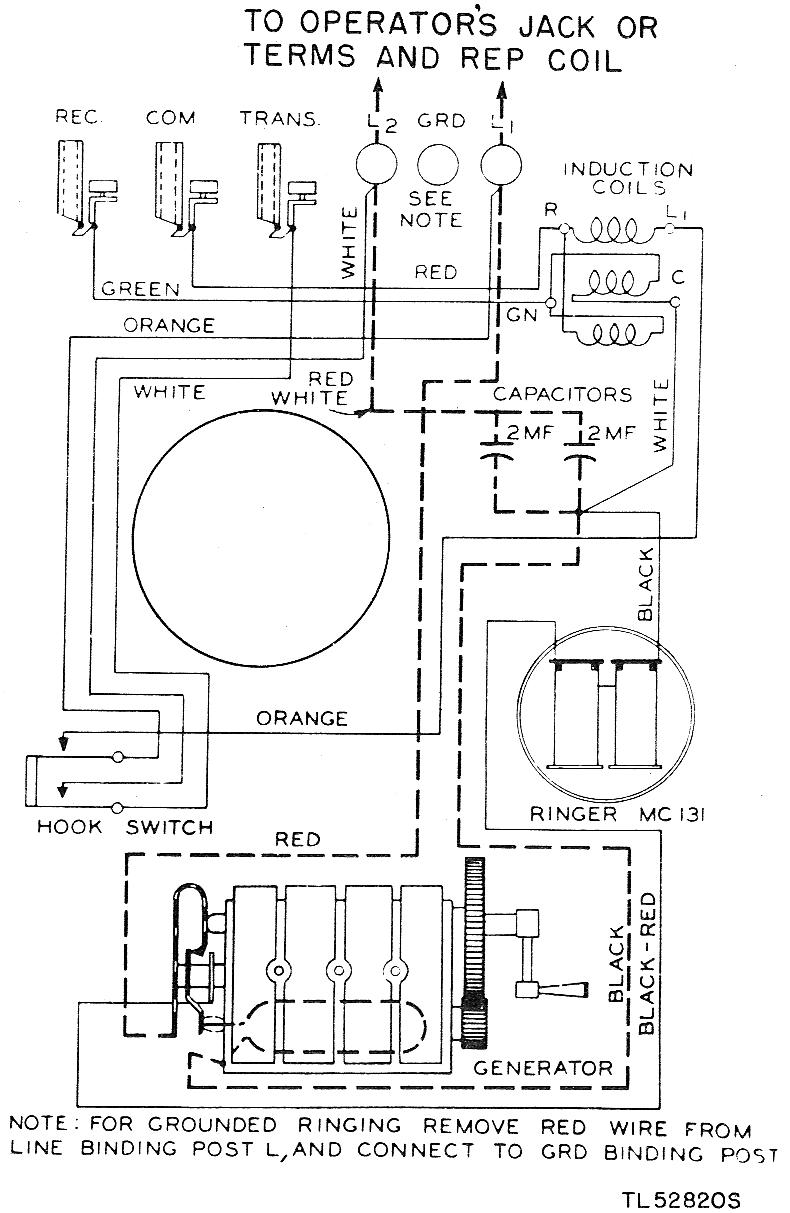
The EE-91 is a wall-mounted metal telephone box. It is a common battery phone, meaning the transmitter current is sourced from the central office battery. It features a single gong ringer and is equipped with a hand generator for...
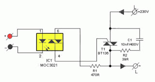
The primary advantage of a solid-state relay (SSR) over a traditional electromagnetic relay (EMR) is its reduced wear and tear, which enhances its longevity. The S201S01 model from Clear-Cut serves as an exemplary representation of this technology. The following...
The circuit is compatible with all 2323 chips, but it is optimized for the AT90LS2323, which operates at a voltage range of 2.7 to 6 volts. The microcontroller utilized in this design is the AT90S2323, which functions effectively within...
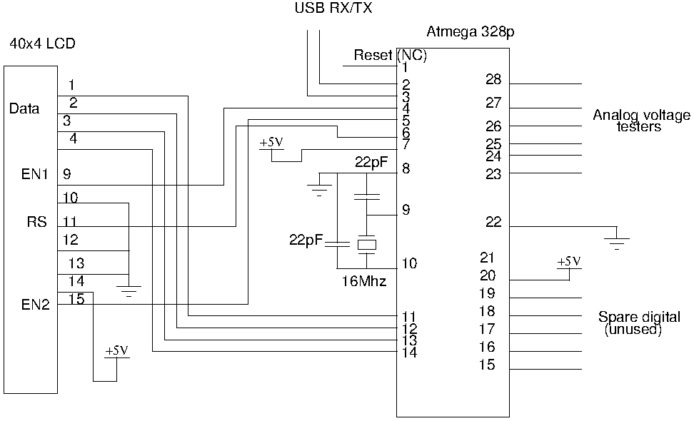
Drive a four-line LCD panel using an Arduino. The project initially aimed to control the LCD for displaying arbitrary information but evolved to include functionalities such as timekeeping, EEPROM read/write operations from the Atmel 328p, and voltage measurement. Multiple...

This is a simple hobby circuit for a remote-controlled toy car. The primary component utilized is the IR sensor circuit, which includes a TSOP IR receiver. This receiver allows the user to start and stop the DC motor of...

The Wildcard requires a minimum of 8 volts on the V+Raw power rail, which must not exceed 26 volts. When using the Docking Panel or Power Dock, the V+Raw rail is automatically connected. If not using a dock, manual...
Warning: include(partials/cookie-banner.php): Failed to open stream: Permission denied in /var/www/html/nextgr/view-circuit.php on line 713
Warning: include(): Failed opening 'partials/cookie-banner.php' for inclusion (include_path='.:/usr/share/php') in /var/www/html/nextgr/view-circuit.php on line 713