
DK-1 type control box using the AC electromagnet closing circuit
The DW15-200-630A breaker solenoid is integral to the operation of circuit protection systems, specifically designed to engage and disengage electrical circuits under controlled conditions. The solenoid operates on direct current (DC) and is intended for short-duration applications, making it suitable for environments where rapid actuation is necessary.
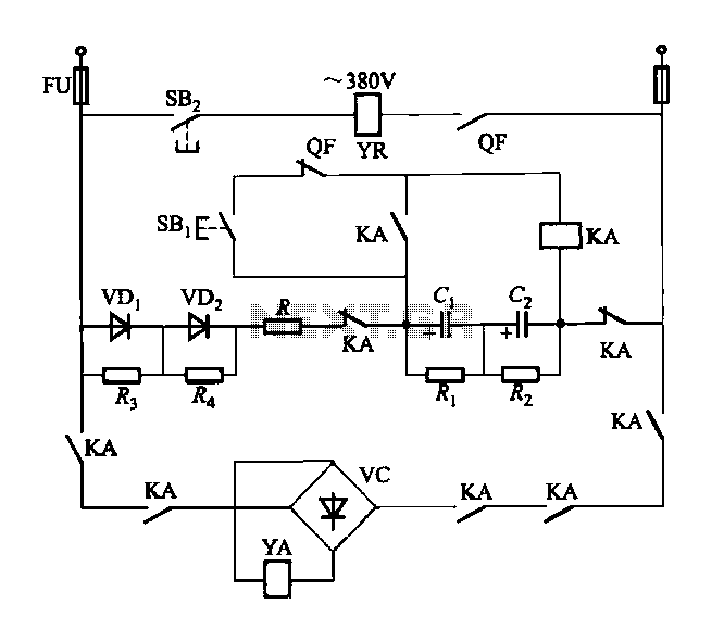
The DK-1 control box plays a crucial role in managing the solenoid's operation. The inclusion of an AC power switch allows for the energization of the electromagnet circuit, which is essential for the solenoid's functionality. The control box is equipped with a closing button (SBi) and an opening button (SBz) that provide manual control for the solenoid's operation. When the closing button is pressed, the solenoid coil (YA) is energized, causing the solenoid to actuate and close the circuit. Conversely, pressing the opening button (SBz) deactivates the solenoid, allowing the circuit to open.
The trip coil (YR) is an important safety feature that enables the circuit to be opened automatically under fault conditions. The intermediate relay (KA) serves to amplify the control signals, ensuring reliable operation of the solenoid and enhancing the overall responsiveness of the circuit protection system.
In addition to these primary components, the control box includes resistors (Ri to R4) that are used for current limiting and voltage division, ensuring that the circuit operates within safe parameters. The storage capacitors (Ci and C2) are critical for smoothing out voltage fluctuations and providing stable operation of the solenoid, particularly during rapid switching events.
Overall, the DW15-200-630A breaker solenoid and its associated DK-1 control box represent a robust solution for electrical circuit control, combining manual and automatic features to enhance operational safety and reliability.DW15-200-630A breaker solenoid DC solenoid structure, short-time working. (1) DK-1 control box using AC power switch on the electromagnet circuit circuit is shown in Figure 6-7 4. DK-1 type of electromagnetic control box. Figure, SBi is closing button, SBz the opening press button, YA is closing solenoid coil, YR for the trip coil, KA intermediate relay, QF circuit breaker auxiliary contacts, Ri ~ R4 are as resistors, Ci, C2 as the storage capacitor.
Related Circuits

The ESR Meter is essentially an AC Ohmmeter equipped with specialized scales and protective circuitry. It provides continuous readings of series resistance in electrolytic capacitors. Operating at 100 kHz, it maintains the capacitive reactance factor close to zero. The...
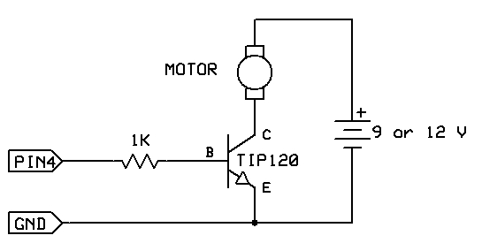
The strategy involves assembling the circuit in stages, testing each component as it is integrated. Once all connections are established and can be controlled or read correctly by the computer, the main program can be developed with assurance that...
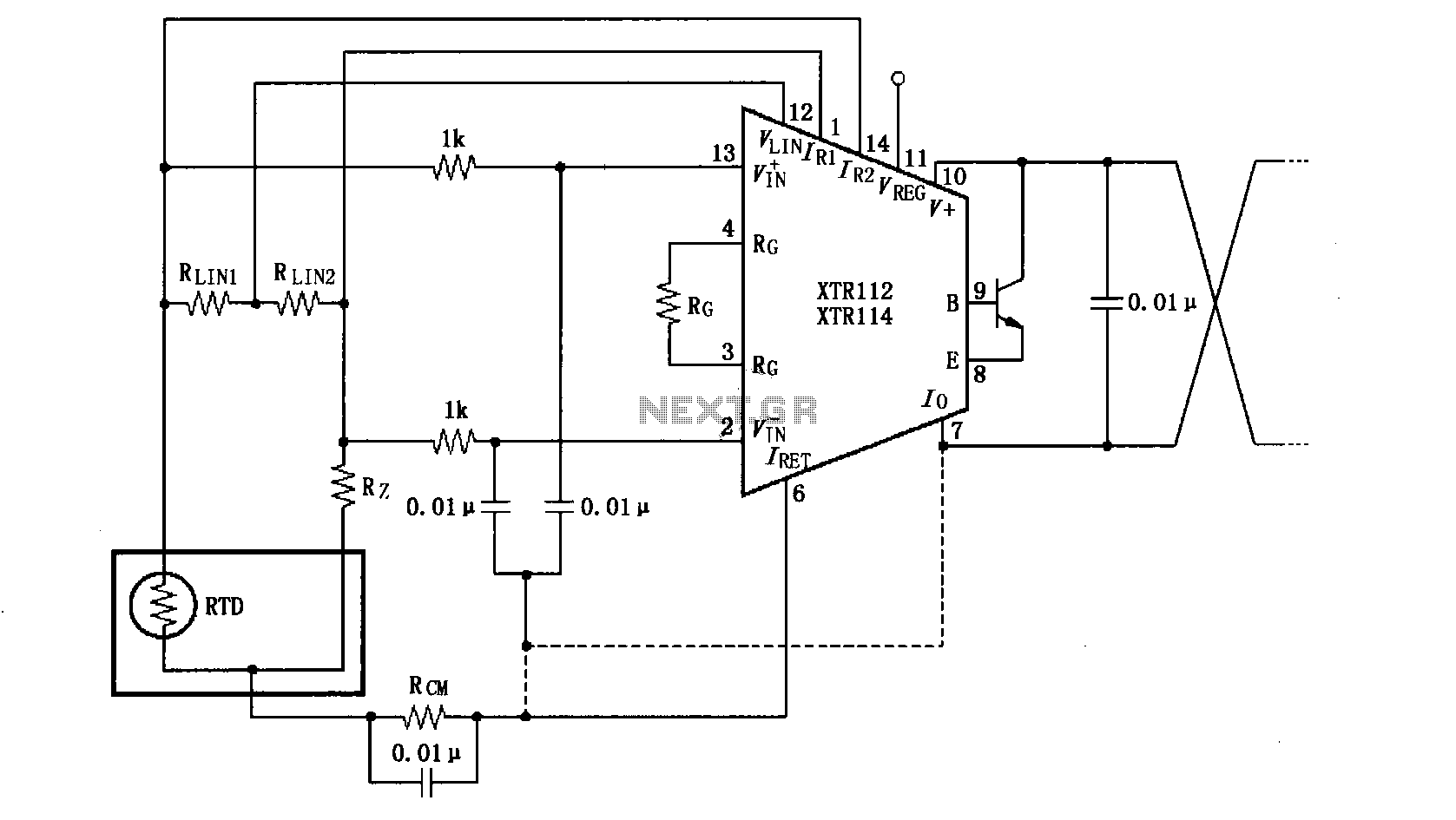
The length of the transmission wire in a current loop circuit can introduce radio frequency (RF) interference. This RF energy may lead to input errors in sensitive devices such as the XT112/114, causing instability in loop current or input...
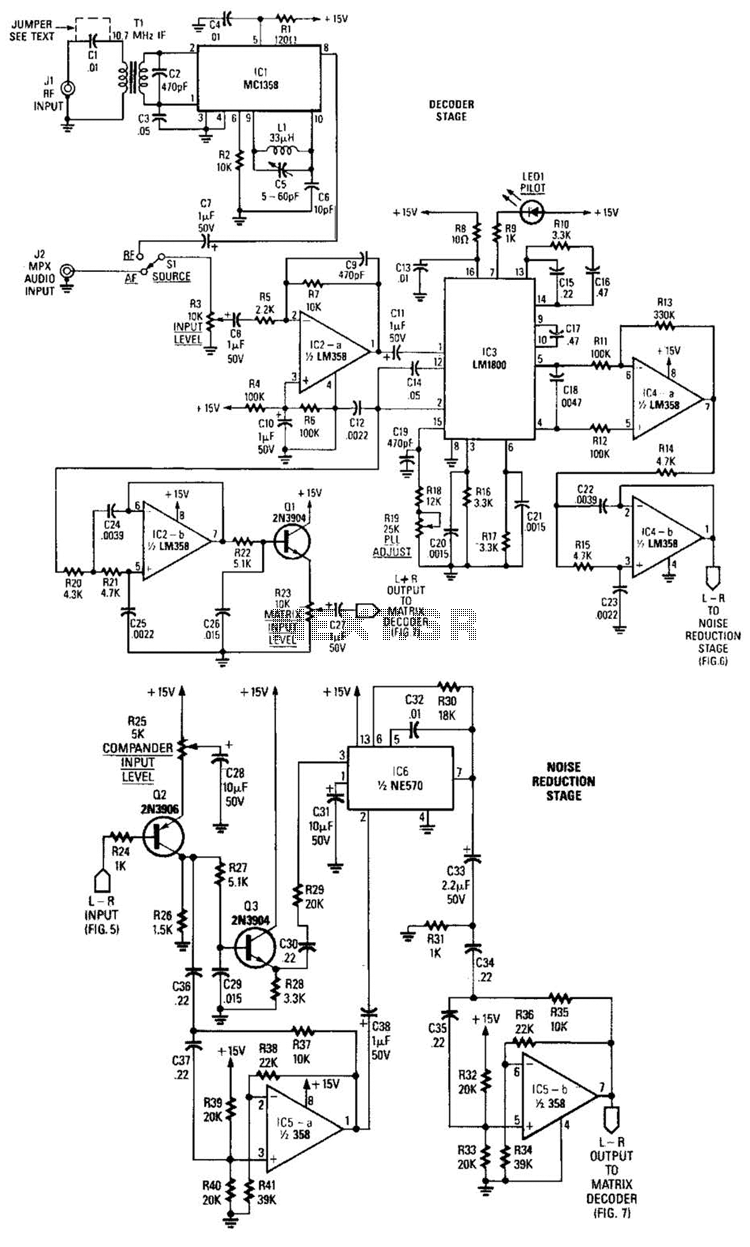
A block diagram of the stereo-TV decoder illustrates the overall relationships between the distinct sections of the circuit, while additional details of each subsection are provided. The decoder section is centered around TCI, a standard 4.5-MHz audio demodulator. The...

The objective of the circuit is to create an electronic dice using the functionality of a 555 timer integrated circuit operating in astable mode. The electronic dice circuit utilizes a 555 timer configured in astable mode to generate a series...
This circuit provides a straightforward and efficient method for interfacing two relays in switching applications. The relay driver utilizes a standard BC547 NPN transistor (or equivalent) to enhance the input impedance. It is a widely used driver capable of...