
Doorbell with IC555
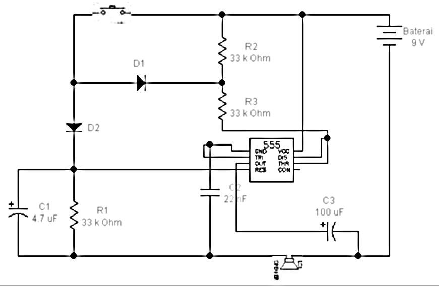
The circuit described utilizes a 555 timer integrated circuit (IC555) configured in astable mode to generate audio tones. In this arrangement, the switch serves as a control element to toggle between two distinct frequencies. When the switch is closed, the circuit is activated, allowing current to flow from the power source through the diode. The diode is crucial in ensuring that current only flows in one direction, thus protecting the circuit components from potential reverse polarity damage.
Current flowing through D1 is directed towards a resistor (R3) and then into pins 6 and 7 of the IC555. Pin 7 discharges the timing capacitor, influencing the frequency of the generated tone, while pin 6 monitors the voltage across the timing capacitor to determine when to reset the timing cycle. The division of current at D2 into three paths allows for additional components, such as polar capacitors, to shape the audio output. The inclusion of polar capacitors ensures that the circuit maintains the required voltage levels for proper operation.
The reset functionality provided by pin 4 of the IC555 is essential for controlling the timing intervals. By applying a reset pulse of 0V to this pin, the timing cycle can be interrupted, allowing the user to modify the output tone as needed. The connection of the speaker to the output of the IC555 enables the audible tone to be produced, with the negative terminal of the speaker grounded through C3 to complete the circuit.
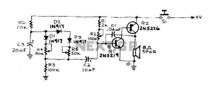
Overall, this circuit exemplifies a simple yet effective method for generating audio tones using a 555 timer IC, with the switch facilitating user control over the tone frequency. The careful arrangement of components ensures reliable operation and clear sound output.All components arranged as in the picture sequence below. Current will flow starting from the sourcevoltage and to the switch. When the switch is closed current will flow through the diode, wherediode serves as a switch is closed because it was given forward bias (anode diode is givenpositive voltage and the cathode is given a negative voltage). F lows will be divided into two to D1 andD2. Flows from D1 (diode 1) will be channeled towards R3 and proceed toward IC555 pin7 andpin 6. Pin 7 (Discharge) serves as an audible tone interval timing, and pin 6 (threshold) to determine the final timing tone, flow at D2 will be divided into three, headingpolar capacitors, resistors, and IC555 pin 4. Polar capacitors are capacitors that havepoles. The current through the capacitor and R1 polar probe + will go to the speakers. IC555 pin 4is reset, as the timing interval can be interrupted by giving the reset pulse 0V. IC555pin 4 is connected to the speaker probe +. Speaker probe - will be connected with C3(capacitor 3) and grounded out, and the probe - the speakers will be connected with the sourcevoltage -.
The working principle of the Bel 2 tone in which the DC voltage source is given in the IC555serves as a timer tones, and used the switch that serves as a voter tonehigh (when the switch is turned ON) and low tone (when the switch position OFF). 🔗 External reference
Related Circuits
An interesting hobby circuit of a crank doorbell. The circuit is built around a 555 timer and a musical piezo buzzer. It operates using a 9-volt battery supply; a single 9-volt PP3/6F22 compact battery is sufficient to power the...
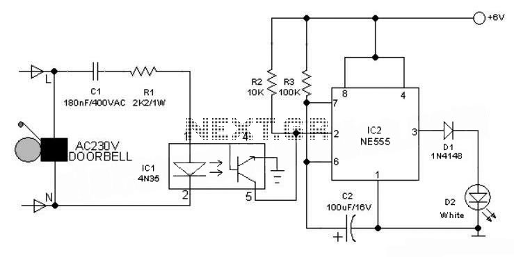
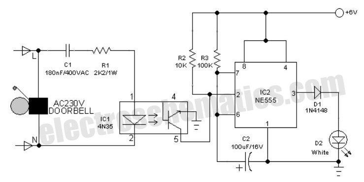
This 6V battery-operated doorbell light circuit can be connected in parallel with any existing AC 230V doorbell. When the doorbell switch is pressed, the bell sounds as usual, and the AC mains supply available across the doorbell is routed...
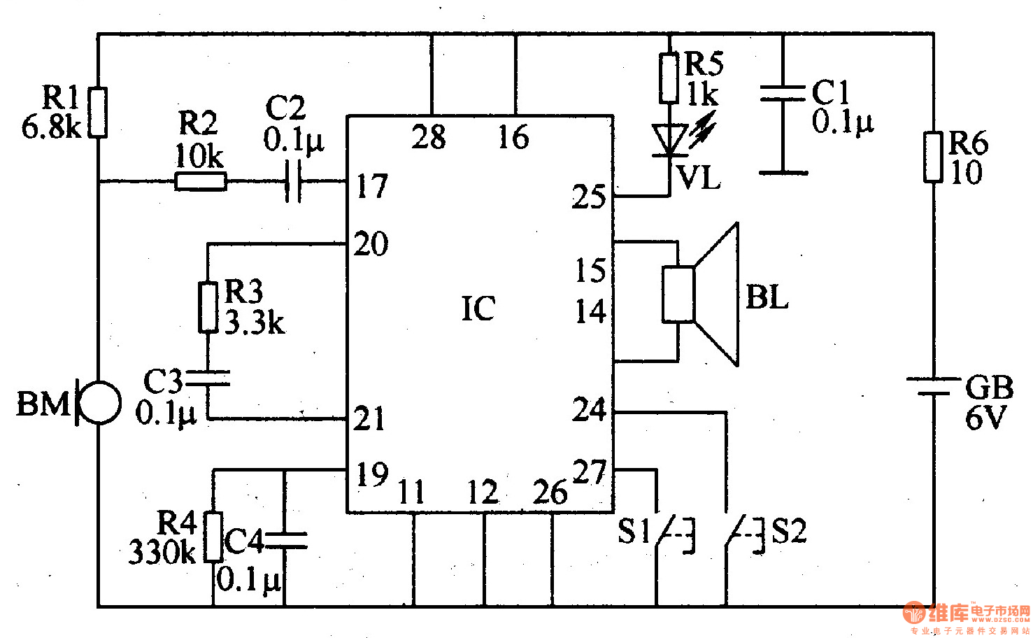
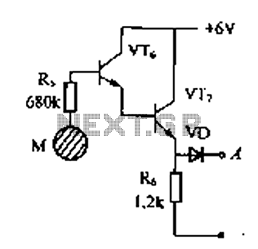
The recordable electronic doorbell consists of a recording and playback integrated circuit (IC), resistors R1-R6, capacitors C1-C4, a microphone (BM), a speaker (BL), control buttons S1 and S2, a battery (GB), and an LED (VL). Resistors R1-R5 should be...
Delay electronic doorbell circuit - touch doorbell amplifier circuit The delay electronic doorbell circuit is designed to provide a user-friendly interface for doorbell activation, utilizing a touch-sensitive amplifier circuit. This circuit typically incorporates a touch sensor that detects user interaction,...

This is a circuit design for a doorbell that produces a sound resembling that of a bird. The circuit is controlled by an NPN transistor. The operation begins when P1 is set to an experimental value, starting with approximately...
When the door is pushed, a whisper is heard that transitions to a higher frequency. The oscillator frequency is determined by the audio frequency coupling capacitance, C1, and the resistance connected between the base of transistor Q1 and ground....
Warning: include(partials/cookie-banner.php): Failed to open stream: Permission denied in /var/www/html/nextgr/view-circuit.php on line 713
Warning: include(): Failed opening 'partials/cookie-banner.php' for inclusion (include_path='.:/usr/share/php') in /var/www/html/nextgr/view-circuit.php on line 713