
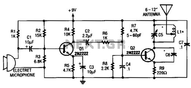
Double limit temperature alarm circuit
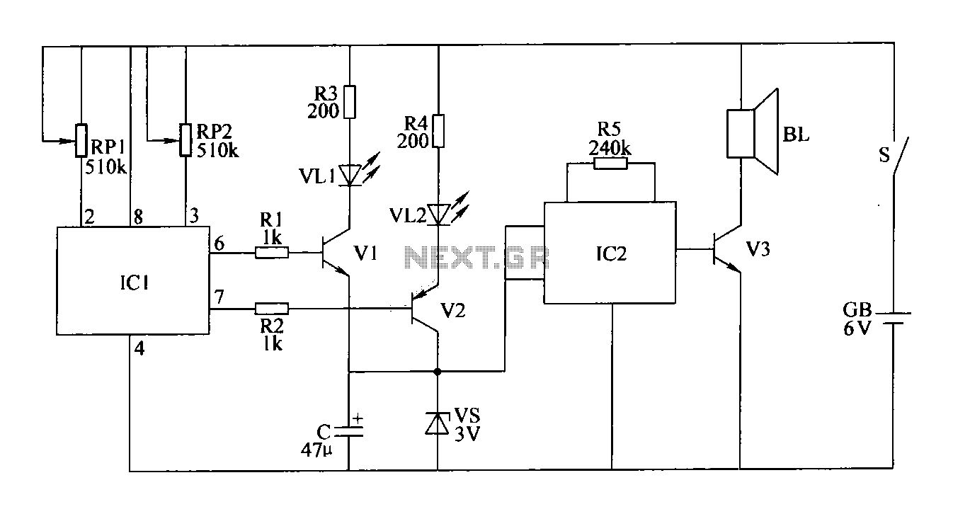
The double-limit temperature alarm circuit is designed to monitor temperature levels and provide visual and auditory alerts when predefined thresholds are exceeded. The circuit operates by utilizing a TC602 temperature sensor (IC1) that detects ambient temperature and outputs a corresponding voltage signal. This signal is processed through a control circuit that compares the voltage against two set limits, defined by adjustable potentiometers RP1 and RP2.
The resistors R1 to R5 form a voltage divider and help set the reference levels for the comparator within the control circuit. The use of 1/4W metal film or carbon film resistors ensures stability and precision in the circuit's performance. The aluminum electrolytic capacitors serve to filter out noise from the power supply, ensuring stable operation of the circuit.
The visual indicators, VL1 and VL2, are high-brightness LEDs that provide clear visual feedback about the circuit's status. The red LED (VL1) indicates that the temperature has exceeded the upper limit, while the green LED (VL2) indicates that the temperature is within the acceptable range.
The alarm sound circuit employs the KD9561 audio integrated circuit (IC2) to generate sound when the temperature exceeds the set limits. The output is connected to a micro speaker (BL) rated at 0.25W and 8 ohms, which produces an audible alarm to alert users of the temperature condition.
Silicon diodes VS are used for rectification and protection within the circuit, ensuring that the components are not subjected to reverse polarity or voltage spikes. The choice of NPN and PNP transistors (V1, V2, V3) allows for effective switching and amplification of signals within the circuit.
The small pole toggle switch (S) is utilized to enable or disable the circuit, providing user control over the alarm system. The entire circuit is powered by a 6V laminated battery (GB), which offers a reliable power source for portable applications.
Overall, this double-limit temperature alarm circuit is a robust solution for temperature monitoring, combining visual and auditory alerts to ensure timely responses to temperature variations.The double-limit temperature alarm circuit by the temperature detection control circuit, the temperature indicating circuit and sound the alarm circuit, as shown in FIG. Components Selection R1 ~ R5 use 1 / 4W metal film resistor or a carbon film resistors. RP1 and RP2 are made of small organic solid potentiometer. C selected voltage is 10V aluminum electrolytic capacitors. VL1 and VL2 select 3mm high-brightness light-emitting diodes, VL1 red, VL2 is green. VS selection 1 / 2W, 3V voltage silicon diodes. V1 and V3 selects S9013 or Model C8050 silicon NPN transistor for use; V2 selects S9015 or Model C8550 silicon PNP transistors. IC1 selects TC602 temperature sensor IC; IC2 selected KD9561 type of audio integrated circuits. BL selection 0.25W, 8 micro-electric speakers. S selection of small pole toggle switch. GB selects 6V laminated battery.
Related Circuits
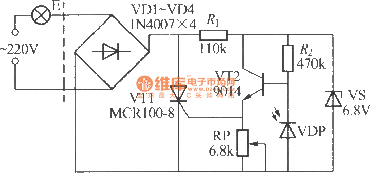
The VDP is a photodiode that exhibits low resistance during the day, approximately 1 kΩ. As a result, transistor VT2 remains off, which keeps thyristor VT1 in the off-state due to the absence of trigger current at the gate,...
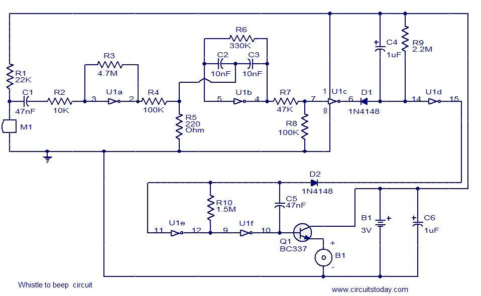
This simple circuit produces a beeping sound that lasts for approximately 3 seconds whenever a whistle is made. The CMOS Hex inverter CD4049 serves as the core component of this circuit. Among the six inverters in the CD4049, U1a...
Dark Activated Switch or Porch Light Switch. This circuit activates a relay when the light level drops below a preset threshold. The light sensitivity can be adjusted using variable resistor VR1, and the relay contacts can control an external...
The vacuum tube remains relevant and functional in certain applications, such as in this continuous wave (CW) transmitter. The circuit is constructed in a traditional breadboard style on a wooden base. Old table radios serve as a valuable source...
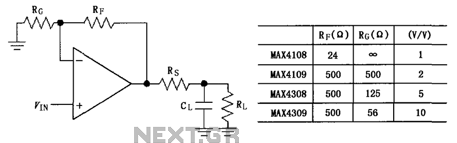
The circuit depicted in the figure employs the MAX4108/4109/4308/4309 operational amplifiers with a capacitive load driving circuit isolation resistor (Rs). While the MAX4108/4109/4308/4309 exhibits excellent AC characteristics, it is not optimized for driving high-load electrical resistances. A significant reactive...
Unlike LED light, a laser's light output is more concentrated, resulting in a smaller and narrower viewing angle. This characteristic necessitates that the laser light be directed more precisely at its source for effective detection. Laser light is also...