
driving stepper motor using uln2003
The ULN2003 is a versatile component commonly used in driving stepper motors, particularly those with lower current ratings. This integrated circuit serves as a relay driver and is particularly advantageous due to its ability to handle inductive loads. The internal Darlington transistor configuration allows for high current gain, providing sufficient drive capability for small to medium-sized stepper motors.
In applications where a stepper motor requires more torque and operates at higher currents, the TIP120 power transistor can be utilized. The TIP120 is a Darlington pair that is capable of managing currents significantly higher than the ULN2003, making it suitable for applications where the motor's power demand exceeds 500mA per channel. It is important to note that while the TIP120 allows for higher current handling, it also introduces additional complexity to the circuit design, as it requires multiple components to achieve the desired control.
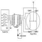
When implementing a stepper motor driver circuit using the ULN2003, it is crucial to ensure proper connection of the stepper motor phases to the output pins of the ULN2003. Each output pin corresponds to a specific phase of the motor, and the sequence of activation must be carefully controlled to enable smooth rotation. The internal clamp diodes are particularly beneficial in protecting the circuit from back EMF generated by the inductive loads, ensuring reliable operation.
In contrast, when utilizing TIP120 transistors for higher current applications, a careful layout and sufficient heat sinking are essential to prevent overheating. The wiring complexity increases as four TIP120 transistors are generally required to control a bipolar stepper motor, necessitating additional consideration for signal integrity and power distribution in the circuit design.
In summary, both the ULN2003 and TIP120 offer unique advantages for driving stepper motors, and the choice between them should be based on the specific current requirements and operational conditions of the application. Proper circuit design and component selection are critical to achieving optimal performance and reliability in stepper motor control systems.The simplest way to drive stepper motor having lower current rating is using ULN2003. The ULN2003 contains seven darlington transistors. The ULN2003 can pass upto 500mA per channel and has an internal voltage drop of about 1V when on. It also contains internal clamp diodes to dissipate voltage spikes when driving inductive loads. The circuit for driving stepper motor using ULN2003 is shown below. For higher current torque motors, you can use TIP120. The advantage is that the TIP120 can pass more current along with heat sink. The disadvantages are that the more wiring is required and four TIP120 is used to control the motor. 🔗 External reference
Related Circuits
The frequency formula of a 555 oscillator is well-known. For given resistors and capacitors, the frequency can be calculated using a specific formula derived from mathematical principles. The 555 timer IC is widely used in various applications, including oscillators, timers,...
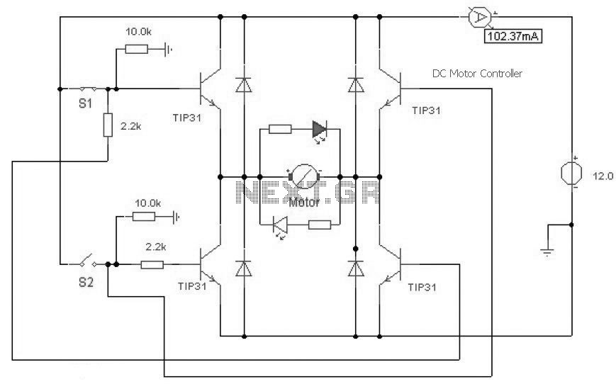
This is a DC motor controller circuit built using a TIP31 transistor based on the H-Bridge concept. The switches S1 and S2 are normally open, push-to-close buttons. The LED serves to indicate the direction of motor rotation. The described DC...
The SN74AVCA406E is a transceiver designed for interfacing microprocessors with MultiMediaCards (MMCs), secure digital (SD) cards, and Memory Stick compliant products. It is manufactured by Texas Instruments. The SN74AVCA406E transceiver is a versatile device that facilitates communication between microprocessors and...
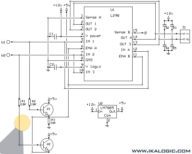
This implementation utilizes the L298 integrated circuit to drive motors and inductive loads with a continuous current capacity of up to 4A. The L298 consists of two independent channels, each capable of driving loads of up to 2A. By...
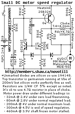
Reverse engineered circuit diagram of a motor speed regulator out of a portable pocket tape recorder containing a single motor for all functions. This circuit works amazingly well, keeping the motor speed constant regardless of shaft load and battery...
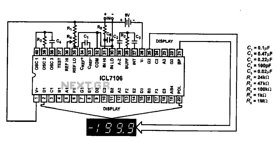
This circuit utilizes the ICL7106 / ICL7107 chip to drive a liquid crystal display (LCD). In this configuration, the ICL7106 / ICL7107 functions as a signal measurement and analog-to-digital (A/D) converter. It detects an analog input signal, amplifies it,...
Warning: include(partials/cookie-banner.php): Failed to open stream: Permission denied in /var/www/html/nextgr/view-circuit.php on line 713
Warning: include(): Failed opening 'partials/cookie-banner.php' for inclusion (include_path='.:/usr/share/php') in /var/www/html/nextgr/view-circuit.php on line 713