
DTMF Decoder 2
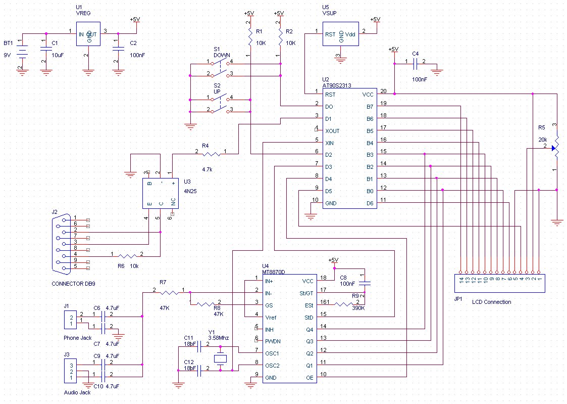
Programming the microcontroller is the next step. The microcontroller used is the AVR AT90S2313 manufactured by ATMEL, and an AVR socket programmer is required. A list of suitable programmers is available, and one can also create a custom AVR socket programmer. It is recommended to replace D1 with a 1N5817 diode and use a 20-pin DIP 0.3" socket instead of the 10-pin connector. A crystal must be connected between pins 4 and 5, and power must be supplied to the microcontroller. Instructions for this process are provided with the specific programmer. If a custom socket programmer is created, Pony Prog, which is free programming software, can be used. The microcontroller should be installed into the DTMF decoder, and upon powering up the device, the contrast should be adjusted until the message "DTMF Decoder" appears on the screen. It is important to note that if the ATTINY2313 is used, the fuse setting should be configured for "external oscillator, 3-8 MHz, 64ms startup time," ensuring that the fuse setting "Divide clock by 8" is not enabled. The program is written in C and consists of one C file intended to be compiled under the free AVR-GCC C compiler (WinAVR version 3.4.3, released February 14, 2005). A beginner's guide is available for those who need assistance with installing GCC. Once GCC is operational, the Project Files for Programmers NotePad can be downloaded and extracted to a chosen directory. Running Programmers NotePad (located at /WinAVR/pn/pn.exe), the user should navigate to "File->Open Project(s)" and select "dtmf2.pnproj" from the directory where "dtmf2.zip" was unzipped. Opening "dtmf2.c" by double-clicking will allow the user to test the compiler by clicking "Tools->Make All." The program is well-documented and self-explanatory. To utilize the DTMF decoder, it should be connected to a 9V battery and the phone line. The DTMF decoder is capable of accepting isolated DC voltages ranging from 7 to 20V for power. Upon power-up, the device will be ready for operation.This device and all information contained on this website is for educational purposes only. This device must be used in conjunction with any and all local, provincial and federal laws. It is up to the end user to comply with all legal guidelines, thus we are not and will not be held responsible for any misuse of this product or any damages that it may cause. The DTMF decoder 2 is a useful tool used for decoding DTMF (Dual Tone Multi frequency) generated by telephones. The decoded digits are viewed on a 16x2 LCD screen. The DTMF decoder can be directly connected to a Serial port to view the digits in HyperTerminal on a computer.
The decoder stores the last 234 received digits in EEPROM. The contents of EEPROM can be viewed on the LCD screen via two scroll buttons. Total power consumption is 12mA. The DTMF decoder has two inputs. A RJ11 jack for connecting to the phone line and a 1/8" audio jack for connecting to a scanner, tape recorder or other audio output device. A PCB layout is provided if one wishes to construct their own PCB. Simply print the file at 1:1 onto an overhead transparency. (Get the correct sheet for your type of printer) I used a kit by MG Chemicals ( E-Sonic Search for 416-K) to produce my PCB.
The provided PCB layout`s smallest traces are 15 thou wide. Drill the holes for the headers at 40 thou. Drill the holes for the 20K POT, the buttons, and the audio jack at 35 thou. Drill the rest of the holes at 30 thou. Drill bits can be found a most hobby stores. Review the schematic and parts placement diagram before beginning assembly for proper orientation of ICs and capacitors. Begin by installing the 7 jumper wires. Next solder in all the resistors and capacitors. Then solder in the buttons, the phone and audio jack, the 20K POT and the crystal. Solder in the 20 pin socket, ICs and 9v battery connector. Next solder the DB-9 connector to the end of the PCB. Short pins 7 and 8 on the DB-9 together by bridging them with solder. At this point, connect power and test the decoder for +5V between pins 10 and 20 on the 20 pin socket.
Finally install the two, seven pin headers into the LCD (short side towards LCD). Solder the longer side of the headers into the DTMF decoder PCB. Attach the LCD and decoder together with hot glue or other means. Programming the microcontroller is the next step. The micro is a AVR AT90S2313 made by ATMEL. An AVR socket programmer is required. Here is a list of programmers. Make you own AVR Socket Programmer. Replace D1 with a 1N5817 and use a 20-pin DIP 0. 3" socket instead of the 10 pin connector. You will have to connect a crystal between pins 4, 5 and supply power. to the micro. Instructions are provided with the specific programmer. If you make your own Socket programmer, use Pony Prog which is free Programming software. Install the micro into the DTMF decoder. Power the decoder up, adjust the contrast, and the message "DTMF Decoder by should appear on the screen. NOTE - If you are using the ATTINY2313, set the Fuse setting "external oscillator, 3-8 Mhz, 64mS startup time".
Make sure that the Fuse setting "Divide clock by 8" is NOT set. The program is written in C. It consists of one C file and was written to be complied under the free AVR-GCC C compiler (WinAVR 3. 4. 3 February 14, 2005). Read the beginners guide to learn how to install GCC. Once you have GCC working, download the Project Files for Programmers NotePad. and unzip them to a directory of your choosing. Run Programmers NotePad ( /WinAVR/pn/pn. exe). In PN go "File->Open Project(s)" and select "dtmf2. pnproj" in the directory where you unzipped "dtmf2. zip". Open "dtmf2. c by double clicking on it. Click "Tools->Make All" to test the Compiler. The program is well documented and self explanatory. To use the DTMF decoder, simply connect it to a 9V battery and the phone line. The DTMF decoder will accept ISOLATED DC voltages from 7 to 20 V for power. Upon power up 🔗 External reference
Related Circuits
The four data lines from the Keypad Interface connect directly to the data inputs of the Holtek 9200B DTMF Generator (pins 6, 7, 8, and 9). The Inverted Chip Enable output from the Keypad Interface is connected to the...
This is an image Schematic. No Description available. The provided input indicates that there is a schematic image, but no additional descriptive information is available regarding its components, functionality, or application. In the context of electronic schematics, such images...
The main system consists of the user interface and control system. The phone line was selected as the interfacing method due to its advantages in long-distance communication. The subsequent image provides a block diagram for both the remote access...
A DTMF-based infrared (IR) transmitter and receiver pair can be utilized to create a proximity detector. This circuit enables the detection of any object capable of reflecting the IR beam and moving in front of the IR LED and...
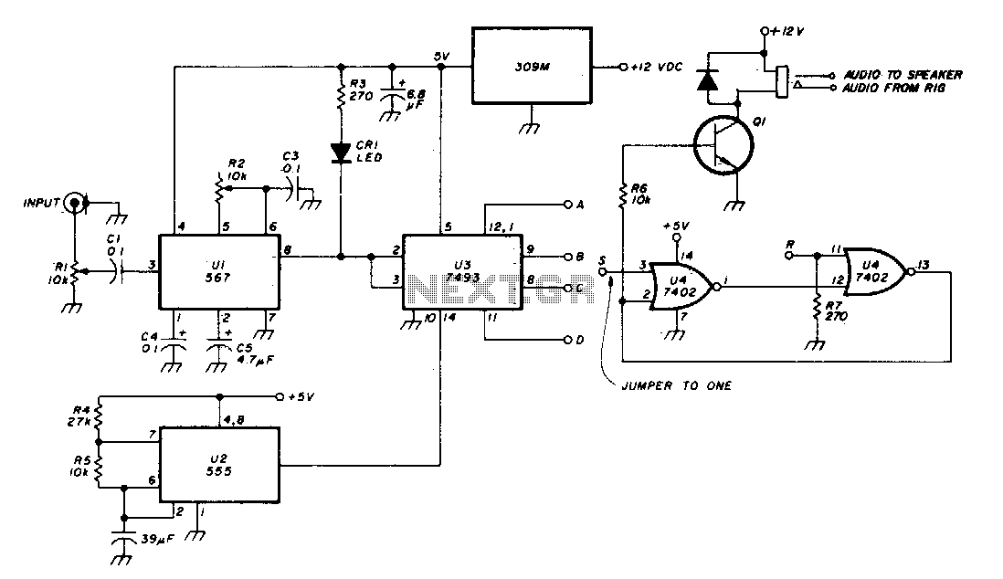
The Phase-Locked Loop (PLL) integrated circuit (U1) is configured with resistor R2 to achieve the desired tone frequency. An LED indicator is used to show when the PLL has locked onto the signal. To ensure proper lock-up, the signal...
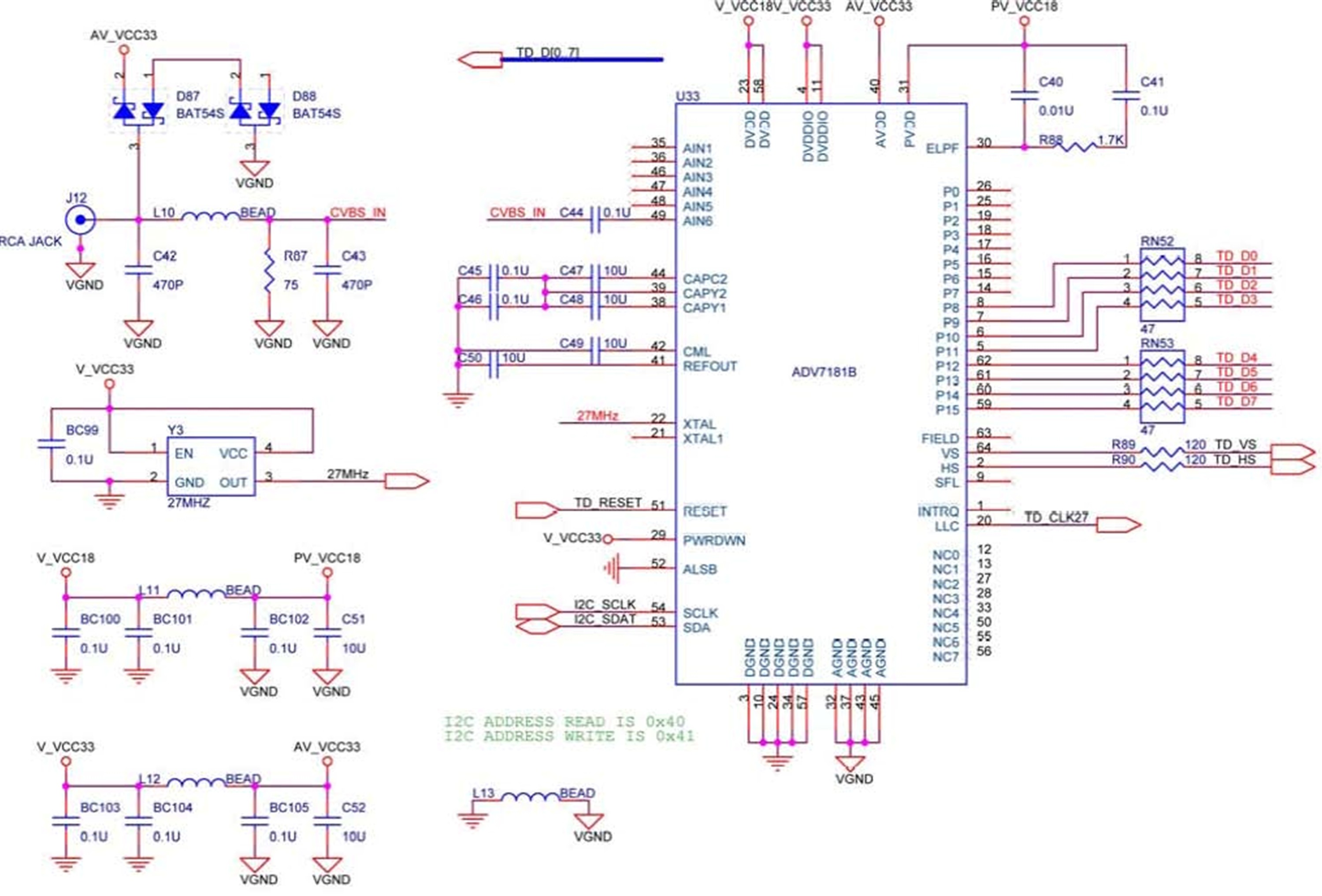
The DE2 board features an Analog Devices ADV7181 TV decoder chip. The ADV7181 is an integrated video decoder that automatically detects and converts standard analog baseband television signals (NTSC, PAL, and SECAM) into 4:2:2 component video data, which is...
Warning: include(partials/cookie-banner.php): Failed to open stream: Permission denied in /var/www/html/nextgr/view-circuit.php on line 713
Warning: include(): Failed opening 'partials/cookie-banner.php' for inclusion (include_path='.:/usr/share/php') in /var/www/html/nextgr/view-circuit.php on line 713