
DTMF Multi-channel code decoding infrared remote control circuit

The infrared emission circuit in Figure (a) employs a 12-key keyboard to facilitate user input, where each key corresponds to a specific infrared signal generated by the S2559 infrared emitter. The S2559 is a compact, high-performance infrared emitter that operates efficiently within the designated wavelength range, ensuring reliable communication in various applications.
Figure (b) features the DTMF (Dual-Tone Multi-Frequency) decoder circuit, which is primarily based on the MT8870 integrated circuit. This circuit is designed to decode the dual-tone signals produced by the keypad input. The MT8870 processes the audio signals and converts them into digital signals, which can be used for further processing or control within the system. Additionally, the channel control circuit manages the routing of the decoded signals to the appropriate outputs, allowing for effective communication and control in telecommunication applications.
In Figure (c), the voltage amplifier circuit utilizes two LM358 operational amplifiers to amplify the input signal. The LM358 is a dual operational amplifier that provides high gain and bandwidth while maintaining low power consumption. This circuit configuration allows for a significant increase in signal strength, making it suitable for applications that require precise signal amplification. The use of two op-amps enables differential amplification, which can help reduce noise and improve overall signal integrity.
Overall, these three figures represent essential components of a comprehensive electronic system, integrating user input, signal decoding, and amplification to achieve effective communication and control.Figure (a) is the infrared emission circuit that composed of 12 the keyboard and S2559. Figure (b)shows DTMF decoder circuit and channel control circuit composedof the MT8870. Figure (c) is the voltage amplifier circuit composed of two-op ampLM358.. 🔗 External reference
Related Circuits
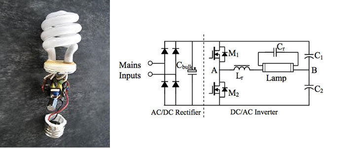
A circuit diagram for a 40W, 230V transistor-based electronic ballast is required. What steps are involved in designing an electronic ballast? An electronic ballast is a device used to regulate the current to fluorescent lamps and provide sufficient voltage to...

Similar to the CMOS-based touch switch available on this site, this transistor-based touch switch can activate a load simply by the user touching a metal plate. It is designed to directly switch a relay, allowing it to be used...
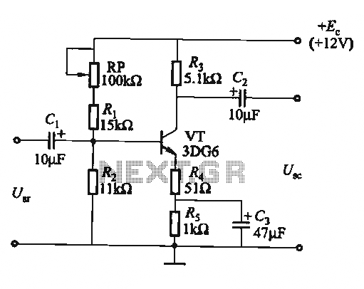
The circuit is a bias circuit for automatic stabilizers that maintains a stable quiescent operating point with good thermal stability. It utilizes a three-pole tube with an NPN type transistor, characterized by a small Iceo. An adjustment potentiometer, RP,...
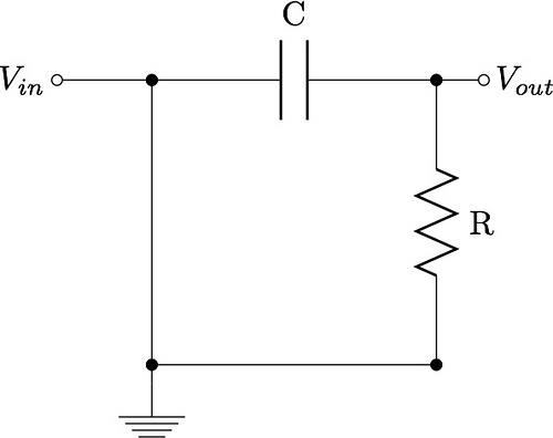
This guide aims to demonstrate the construction of various filter circuits, specifically low pass and high pass filters, along with additional details. The construction of filter circuits is essential in many electronic applications, as they allow for the selective passage...
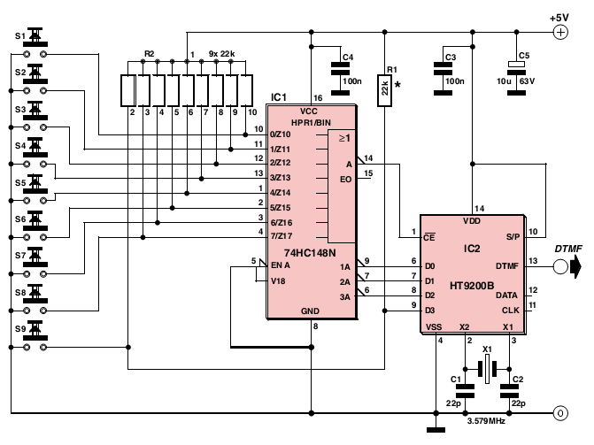
The signal is encoded as a pair of sine waves, ensuring that no frequency is a multiple of the other, and that the sum and difference between the two frequencies do not match any single tone, which contributes to...
L1 is 0.112uH (this tunes to the middle of the FM band, 98 MHz, with VC1 at its centre value of 33pF). L1 is 5 turns of 22 swg enamelled copper wire close-wound on a 5mm (3/16") diameter former....