
dual power supply with soft power switch
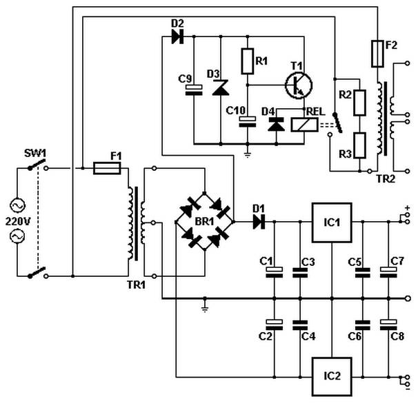
The described soft power circuit is designed to manage the inrush current that occurs when a large transformer is energized. Inrush current can lead to potential damage to components and cause circuit instability. By incorporating a series resistor of 100 ohms, or two 47-ohm resistors in parallel, the circuit limits the initial current flow, allowing for a gradual increase in voltage across the transformer. This method enhances the longevity and reliability of the transformer and associated components.
The relay plays a critical role in the operation of this soft power circuit. After a predetermined delay of approximately 1.5 seconds, the relay activates and shorts the series resistance. This transition allows the transformer to operate under normal conditions without the resistive drop, thus improving efficiency. The use of a Zener diode in the circuit provides versatility, as it can be set to accommodate different voltage levels for various relay types. This adjustability ensures compatibility with a range of transformers and power supply configurations.
The dual power supply with a soft power switch design further enhances the functionality of the circuit by allowing for controlled power delivery to multiple outputs. This design is particularly beneficial in applications requiring stable voltage levels and minimal electrical noise, making it suitable for sensitive electronic devices and systems. The schematic diagram associated with this power supply circuit provides a visual representation of the components and their interconnections, aiding in both understanding and implementation.Soft power for a large transformer is made by taking the series resistance of 100 ohms/10 watt or two resistors 47 ohm / 5 watts in the primary circuit, the resistance is shorted by the relay after ± 1. 5 seconds. This avoids a sudden use of the current during power up. A Zener diode can be adjusted to allow theuse of various voltage relay. The schematic diagram come from circuit: Dual Power Supply with Soft Power Switch power supply. Go to that page to read the explanation about above power supply related circuit diagram. 🔗 External reference
Related Circuits

High brightness (HB) and super HB LEDs are utilized in LCD TFT backlighting for high-end televisions, industrial lighting, and projectors. A notable application is in instrument panel backlighting, interior lighting, and brake lights of various vehicles. Luxury automobile manufacturers...
The wide variety of automotive motor drivers, including those used for HVAC (heating, ventilation, and air conditioning), headlamp, seat positioning, window, and mirror applications, necessitates circuits that perform more than just switching the motor on and off. The drivers...
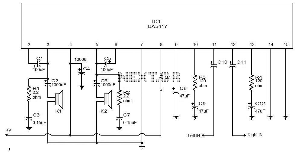
The BA5406 is a dual OTL (output transformerless) monolithic power integrated circuit (IC) featuring two high-output speaker amplifier circuits. It operates effectively with a supply voltage (Vcc) of 12 V and a load resistance (Rl) of 3 Ohms. At...
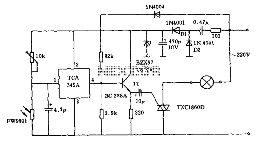
A 200W lamp switch control operates at a power supply voltage of 220V. It automatically turns the light on or off based on ambient illumination levels, specifically activating at approximately 100 lux. In low light conditions, a time-sensitive resistor...
This is a simple circuit of a low-power voltage regulator reference. This circuit can produce a stable voltage reference. The low-power voltage regulator reference circuit is designed to provide a consistent output voltage, which is crucial for various electronic applications...
This circuit is a small +5V power supply, which is useful when experimenting with digital electronics. Small inexpensive wall transformers with variable output voltage are available from any electronics shop and supermarket. Those transformers are easily available, but usually...
Warning: include(partials/cookie-banner.php): Failed to open stream: Permission denied in /var/www/html/nextgr/view-circuit.php on line 713
Warning: include(): Failed opening 'partials/cookie-banner.php' for inclusion (include_path='.:/usr/share/php') in /var/www/html/nextgr/view-circuit.php on line 713