
Dummy Transmission Circuits for Subcutaneous Transmitter
The described project focuses on developing a compact transmitter for biological applications, specifically for implantation in small animals like rats. The transmitter's ability to handle data efficiently while maintaining a low power consumption profile is critical for ensuring long-term operation on a limited power source, such as a lithium battery. The design emphasizes a modular approach, allowing for iterative testing and refinement of both the transmitter and receiver components.
The transmitter's design variants illustrate the versatility in antenna configuration, which is crucial for optimizing performance in varying environments. The loop antenna design in the A3002A model, for instance, demonstrates effective radiation characteristics due to its size and configuration, allowing for a significant transmission range. The second variant, A3002B, showcases adaptability in antenna choice, enabling effective transmission through different mediums, including water, which is relevant for biological applications where the transmitter may be submerged or encapsulated.
Comprehensive testing protocols will be essential to validate the performance metrics of these devices. Suggested tests may include range testing, power output measurements, and data integrity assessments under various conditions. The results from these tests will inform further refinements and the development of subsequent stages, ensuring that the final product meets the stringent requirements for implantation and reliable data transmission in a living organism.
In conclusion, the project represents a significant advancement in the field of biomedical electronics, with the potential to enhance research capabilities in neurology and related disciplines. The focus on miniaturization, efficiency, and performance will contribute to the successful integration of these devices in biological studies, paving the way for future innovations in implantable technologies.Developing a transmitter small enough to be implanted in the body of a rat, fast enough to transmit four hundred sixteen-bit data samples per second, powerful enough to be detected at a range of three meters, and efficient enough to operate for three months on alithium battery. We divided our development into four stages, each of which we committed to complete within a number of weeks of
receiving payment for the previous stage Open Source Instruments (OSI) submitted its Technical Proposal in November 2004, together with one Miniature Transmitter ( A3001D ) and one Downshifting Receiver ( A3001B ). This completed Stage One of development. OSI invoiced ION (Institute of Neurology) for £3000 and received payment on 18 January 2005. On 16th February 2005, Kevan Hashemi, President, OSI, visited Matthew Walker at ION and brought him four Transmitters with On-Off Switches ( A3002 ), which Kevan demonstrated along with the Downshifting Receiver (A3001B).
On 26th April 2005 OSI shipped two Transmitters with Logic Chips ( A3004 ) and two Demodulating Receivers ( A3005 ) to Matthew at ION by DHL. These final circuits meet our optimistic performance targets, and complete Stage Two of development. On 28th April 2005 OSI sent an invoice by airmail to ION for £5, 000 as agreed upon for the completion of Stage Two.
According to the schedule layed down in its Technical Proposal, OSI Inc. should have delivered its Dummy Transmission Circuits within eight weeks of receiving payment for its Technical Proposal. Even allowing for the time it took for a United Kingdon check to clear through the United States banking system, these circuits were due on 18th March 2005.
As it is, OSI shipped them on 26th April, five weeks late. We did, however, obtain permission from Matthew Walker to delay shipment by several weeks because we believed that in doing so we could supply circuits far superior to the ones we had available in March. Therefore, we believe we are justified in invoicing ION in full for Stage Two of development, even though its completion is at least five weeks behind schedule.
In the following sections we describe the performance of the new transmitters and receivers. We suggest a program of tests for Dr. Walker to perform with them at ION, and we discuss our plans for the next stage of development. Our Transmitter with On-Off Switches ( A3002 ) came in three varieties. All were made on a two-layer printed circuit board without a ground plane. The first variety (A3002A) was 80 mm square, with a quarter-wave square loop antenna around the edge of the circuit board. The transmitter sat at the center of the board, and the board had no ground plane. The loop antenna worked well, and transmitted measurable 1-GHz RF (radio frequency) power to our Downshifting Receiver ( A3001R ) at a range of five meters through air.
The absense of a copper ground plane in the circuit board meant that the loop antenna operated freely in the surrounding air. The second variety of (A3002B) was 18-mm square with a hole in the circuit board for a quarter-wave antenna.
Equipped with a 75-mm antenna in air, this variety transmitted measurable power at a range of five meters also. Equipped with a 15-mm antenna, and enclosed in a latex glove finger, it transmitted measurable power from a cup of water at a range of three meters.
Matthew Walker reported transmission through a silicon coating from within a cup of water at a range of three meters also. The third variety (A3003C) was 18-mm square with a square loop antenna wrapped around the edge of the board.
This variety was intended for use in a cup of water. But it appeared to perform no better in a cup of water than out. In either case, it transmitted measurable power over no more than one meter. We concluded that the battery, which sits in the middle of the transmitter 🔗 External reference
Related Circuits
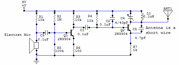
This circuit uses a small microphone to capture the sound and some transistors to generate radio waves that can be picked up by a FM receiver like a car stereo. The first part is the microphone and some resistors...
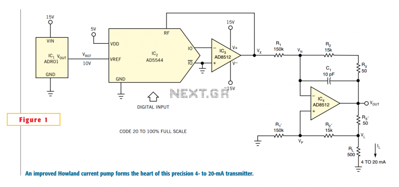
One of the key challenges in the design of 4- to 20-mA current transmitters is the voltage-to-current conversion stage. Conventional transmitters use multiple op amps and transistors to perform the conversion function. These approaches have been around for a...
This application note explains how the transfer function of most operational amplifier circuits can be derived through a straightforward process of nodal analysis. The transfer function of operational amplifier (op amp) circuits is a critical aspect for understanding their behavior...

This is a simple 2N2222 transistor-based FM transmitter circuit that operates within the FCC (Federal Communications Commission) limits, meaning no license is required for its use. FM stands for Frequency Modulation, which is a method of transmitting radio frequency...
This is a very simple project using a printed circuit board and 8 components. It will flash an ordinary 3mm or 5mm (1/8" or 1/4") LED at a rate of about one flash per second. This circuit works on...
PC parallel port can be very useful I/O channel for connecting your own circuits to PC. The PC's parallel port can be used to perform some very amusing hardware interfacing experiments. The port is very easy to use when...
Warning: include(partials/cookie-banner.php): Failed to open stream: Permission denied in /var/www/html/nextgr/view-circuit.php on line 713
Warning: include(): Failed opening 'partials/cookie-banner.php' for inclusion (include_path='.:/usr/share/php') in /var/www/html/nextgr/view-circuit.php on line 713