
Duty-Cycle Detector

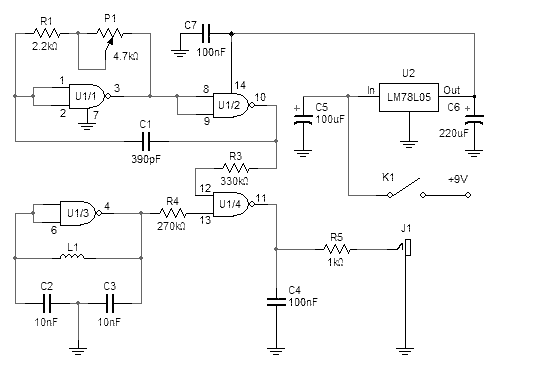
The described circuit functions as a pulse-width discriminator, which is critical in applications where timing and pulse duration are essential for signal processing. The circuit utilizes a comparator or operational amplifier (U1B) to compare the duration of an incoming pulse against a reference value, denoted as VAR1.
In practical terms, when an incoming pulse is detected, the circuit measures the time the pulse remains high. If this duration is less than the threshold set by VAR1, the output of U1B is driven high, indicating that the pulse duration does not meet the required criteria. Conversely, if the pulse exceeds the VAR1 threshold, the output state of U1B may change, depending on the specific design of the circuit.
The circuit can be designed to accommodate various pulse widths, with specific values provided for a pulse duration ranging from 1 to 2 microseconds. This adaptability makes it suitable for a variety of applications, including digital signal processing, timing applications in microcontrollers, and pulse-width modulation systems.
To implement this circuit, it is essential to select appropriate components, including resistors and capacitors, to define the timing characteristics and ensure accurate pulse measurement. The use of hysteresis may also be considered to avoid false triggering due to noise in the incoming signal. Overall, the circuit serves as a reliable means of pulse duration detection, with potential applications in telecommunications, data acquisition systems, and other electronic devices requiring precise timing measurements. This circuit looks at the time an incoming pulse is high. If the incoming pulse is shorter than the adjusted (VAR1) pul se, the output of U1B is high. Values are shown for a 1-to 2-/as pulse. 🔗 External reference
Related Circuits
This simple metal detector requires only a handful of components and an evening's work. Built around a cmos4011 IC, is very robust and versatile. The 250 kHz reference oscillator is built with two gates (U1/1 and U1/2), C1, R1...
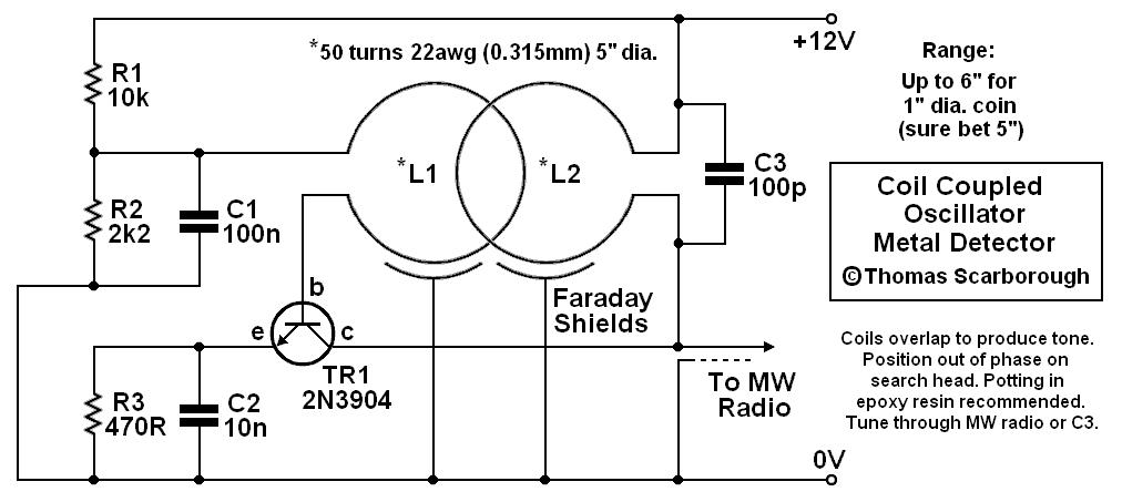
A coil-coupled operation metal detector constructed from commonly available components, utilizing a standard medium receiver as the detection unit. The coil-coupled operation metal detector functions by employing a transmitter coil and a receiver coil that are magnetically coupled. The transmitter...
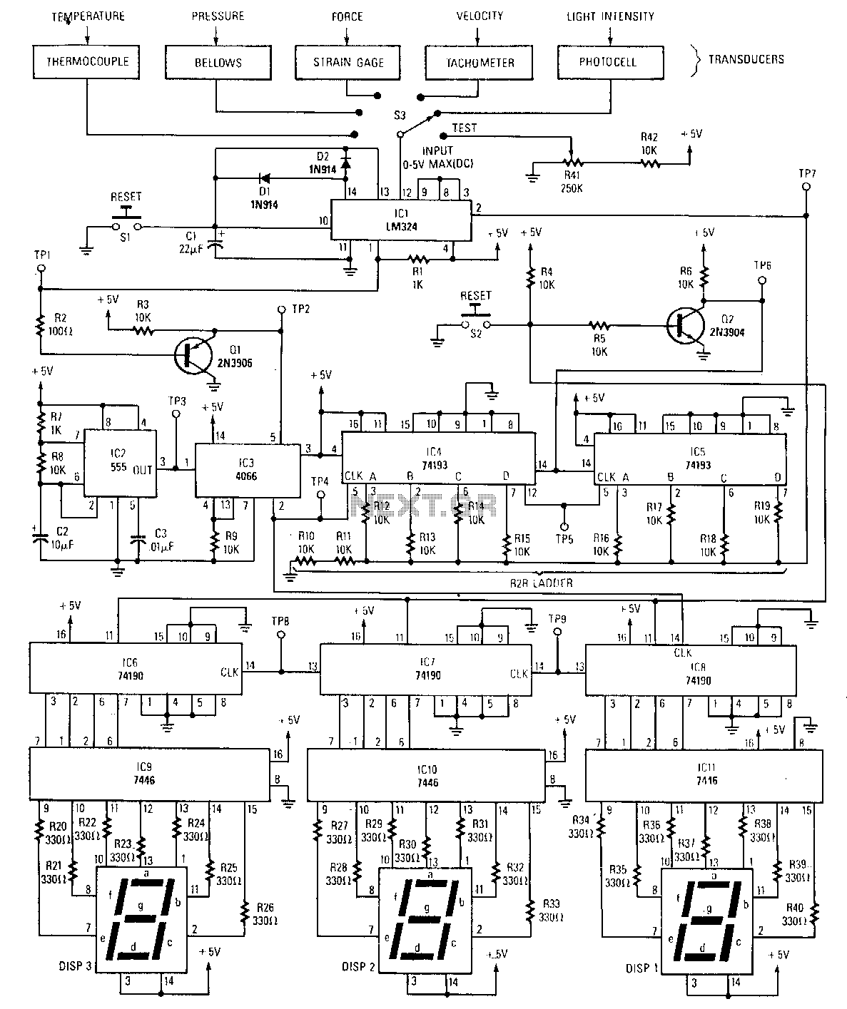
The peak detector tracks and holds the highest output voltage from a transducer by utilizing the charge-storing capability of a capacitor. Initially, the voltage at the inverting input of the comparator is at ground level. When a small voltage...
This circuit can be used as an infrared beam barrier as well as a proximity detector. The circuit uses the very popular Sharp IR module (Vishay module can also be used). The pin numbers shown in the circuit are...
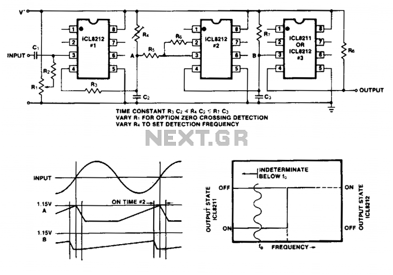
Simple frequency limit detectors providing a GO/NO-GO output for use with varying amplitude input signals may be conveniently implemented with the ICL8211/8212. In the application shown, the first ICL8212 is used as a zero-crossing detector. The output circuit consisting...
The LED phototransistor light gate should be mounted approximately 1 to 2 cm apart, within a rigid housing. It was mounted on a brass piece attached to the circuit board. The housing must accommodate the compass without obstructing the...
Warning: include(partials/cookie-banner.php): Failed to open stream: Permission denied in /var/www/html/nextgr/view-circuit.php on line 713
Warning: include(): Failed opening 'partials/cookie-banner.php' for inclusion (include_path='.:/usr/share/php') in /var/www/html/nextgr/view-circuit.php on line 713