
Dynamic braking circuit control thyristor
The circuit operates by integrating a thyristor for effective braking control, which is particularly advantageous in applications involving small capacity asynchronous motors. The design eliminates the need for a step-down transformer, simplifying the circuit and reducing potential losses associated with transformer use.
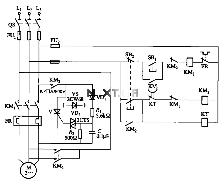
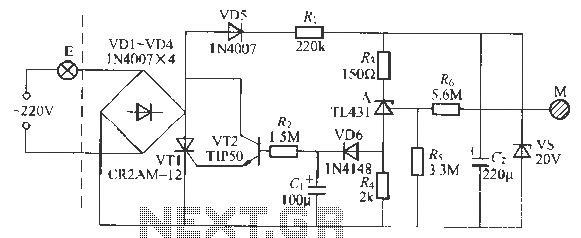
During operation, when the motor is to be shut down, the contactor KM1 is de-energized, allowing contactor KM2 to energize the brake circuit. This energization triggers the thyristor V, which conducts during the positive half cycle of the AC power supply. The conduction of the thyristor allows pulsed DC current to flow to the motor, creating a braking effect that slows down the motor effectively.
The motor remains in a braking state as long as the thyristor is conducting. The circuit is designed with a time delay relay KT, which plays a crucial role in the braking process. The normally closed (NC) contact of this relay remains closed during the braking operation. Once the predetermined time delay elapses, the relay opens its NC contact, causing contactor KM2 to de-energize and subsequently release the brake circuit. This ensures that the braking process is terminated safely and efficiently, preventing any abrupt cessation that could potentially harm the motor or associated components.
Overall, this thyristor-based braking control circuit provides a reliable and efficient means of controlling the braking of small capacity asynchronous motors, enhancing the operational safety and longevity of the motor system. Circuit shown in Figure 3-148. The circuit eliminates the need for step-down transformer, using thyristor for brake control, for small capacity asynchronous motor braking amoun t. When shut down, the contactor KM] release, KM2 pull the brake circuit to work, triggering the thyristor V conduction (per power supply positive half cycle conduction), the motor continues to give effect pulsed DC current braking, the motor is braking status. Until the time delay relay KT break NC contact is opened, the contactor KM2 release, before the end of the braking process.
Related Circuits

The main oscillator is printed in blue and is voltage controlled. In this construction, the VCO range is 88 to 108 MHz. As you can see from the blue arrows, some energy goes to an amplifier and some energy...
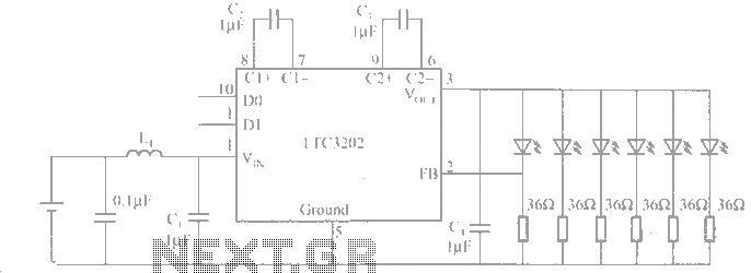
The LTC3202 is a device from Linear Technology that eliminates the need for a charge pump gated oscillator. It is designed as a charge pump for driving white LEDs powered by a lithium-ion battery. To address noise issues, the...
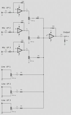
The microphone inputs are amplified approximately 100 times or 40 dB, with the total gain of the mixer, including the summing amplifier, reaching 46 dB. The microphone input is designed for microphones that produce an output of around 2...
This circuit is a church bell controller. Basic component is an ATmega32 microcontroller. At the circuit 1 24LC32 EEPROM memory is being used. As control, a menu is created that appears on a 4x20 LCD (Liquid Crystal Display). The...
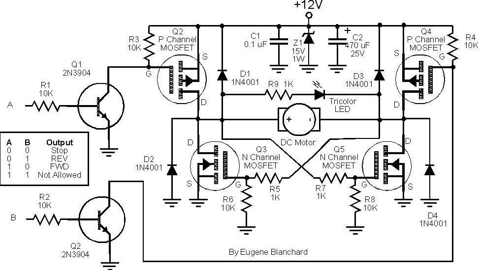
At 9 volts, the maximum stalled current of the motor types intended for use will be 700 mA. The selection of appropriate MOSFETs is crucial, particularly regarding their ratings for current and voltage handling. However, there are concerns about...
This circuit is a touch-sensitive lamp delay switch characterized by minimal static power consumption. It utilizes an external switch terminal, which can directly replace a standard switch. The circuit features a novel precision voltage regulator integrated circuit, such as...
Warning: include(partials/cookie-banner.php): Failed to open stream: Permission denied in /var/www/html/nextgr/view-circuit.php on line 713
Warning: include(): Failed opening 'partials/cookie-banner.php' for inclusion (include_path='.:/usr/share/php') in /var/www/html/nextgr/view-circuit.php on line 713