
Easy-auto-alarm
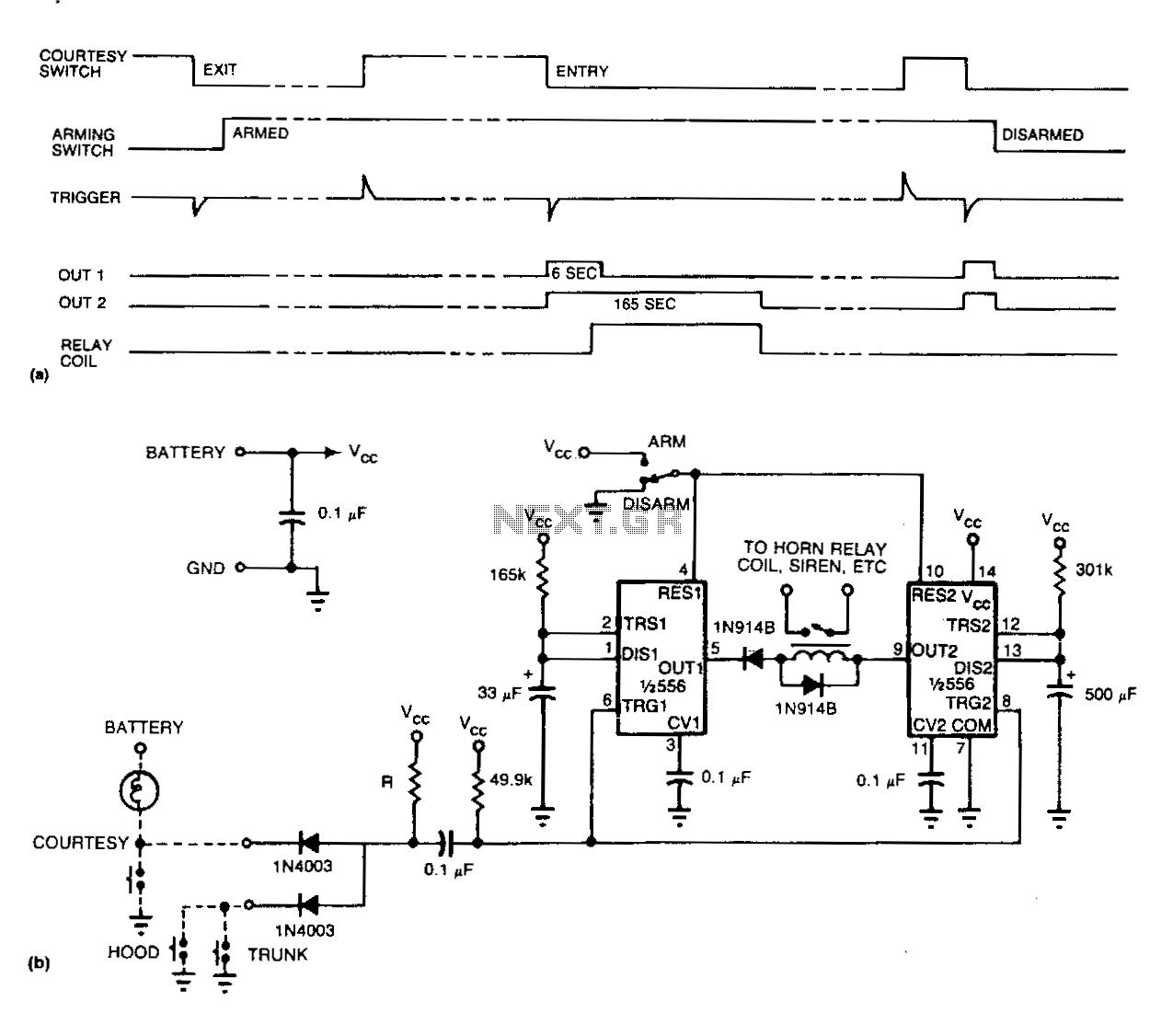
Refer to (a) for the timing information related to the alarm circuit depicted in (b). When departing from the vehicle, the arming switch should be flipped, and the door closed to activate the device. The subsequent opening of an entrance triggers both timers. Upon the expiration of the entry delay timer, the alarm will sound for a duration determined by the second timer. The resistance value of R should be less than 1 kΩ. Utilizing an incandescent lamp in place of a resistor provides an additional function as an open-entrance indicator. Maintaining a low resistance helps prevent false triggering in the event that water accumulates under the hood. If the door switch connects the courtesy light to 12 V instead of ground, a single transistor can be employed as an inverter at the input.
The alarm circuit operates based on two timers that are essential for managing the entry delay and the alarm duration. The first timer is activated upon the opening of the entrance, which initiates a countdown period known as the entry delay. This delay allows the user a brief window to enter the vehicle and disarm the system before the alarm is triggered. The second timer determines how long the alarm will sound once activated, providing a configurable period for the alarm to alert nearby individuals of unauthorized entry.
The component labeled as R plays a critical role in the circuit's performance. A resistor value of less than 1 kΩ is recommended to ensure that the circuit remains responsive while minimizing the risk of false alarms. This is particularly important in environments where moisture may accumulate, such as under the hood of a vehicle. To enhance functionality, an incandescent lamp can serve as a visual indicator of an open entrance, providing a dual purpose for the component.
In instances where the door switch is designed to connect the courtesy light to a positive 12 V supply instead of grounding, the circuit can be adapted using a transistor inverter. This inverter allows the alarm system to still receive the necessary input signal to function correctly, ensuring that the system remains effective regardless of the switch configuration.
Overall, this alarm circuit design provides a reliable solution for vehicle security, incorporating features that enhance its usability and effectiveness while minimizing the potential for false alarms.See (a) for the timing information for the alarm circuit in (b). When leaving your vehicle, flip the arming switch and close the door to arm the device. Subsequent opening of an entrance triggers both timers. After the expiration of the entry delay timer, the alarm sounds for a time determined by the second timer. The value of R should be less than 1 KO. If you use an incandescent lamp instead of a resistor, you get an extra function-an open-entrance indicator.
By keeping the resistance low, you avoid false tripping should water collect under the hood. If your door switch connects the courtesy light to 12 V rather than ground, use a single transistor as an inverter at the input. 🔗 External reference
Warning: include(partials/cookie-banner.php): Failed to open stream: Permission denied in /var/www/html/nextgr/view-circuit.php on line 713
Warning: include(): Failed opening 'partials/cookie-banner.php' for inclusion (include_path='.:/usr/share/php') in /var/www/html/nextgr/view-circuit.php on line 713