
ECG Simulator Schematic
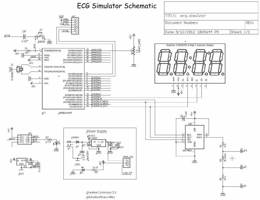
The Menta ECG Simulator project is designed to emulate the electrical signals produced by the heart, providing a valuable tool for testing and calibrating electrocardiogram (ECG) equipment. The schematic incorporates various electronic components that work together to generate realistic ECG waveforms.
The circuit typically includes operational amplifiers configured to create the desired signal shapes, resistors to set gain levels, and capacitors to filter noise and stabilize the output. A microcontroller may also be integrated into the design to allow for programmable waveform generation, enabling the user to simulate different heart conditions by adjusting parameters such as heart rate and rhythm.
Power supply considerations are crucial, with the circuit requiring a stable voltage source to ensure accurate signal generation. Additionally, isolation techniques may be implemented to protect both the simulator and any connected ECG devices from electrical interference or damage.
Output connections are designed to interface seamlessly with standard ECG equipment, often utilizing BNC connectors for ease of use. The final schematic should be thoroughly tested to validate the performance of the simulator under various operating conditions, ensuring it meets the necessary specifications for clinical or educational applications.Below is the final schematic for the Menta ECG Simulator project. LadyAda`s Eagle schematic for the Menta was used as a starting point and I simply ad.. 🔗 External reference
Related Circuits
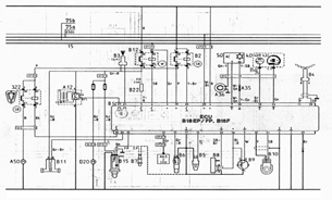
The following document contains information related to the electrical installation schematic diagram for the Volvo 440. It includes the wiring schematic for the Volvo 440, 460, and 480 series. The Volvo 440, 460, and 480 series vehicles feature a comprehensive...
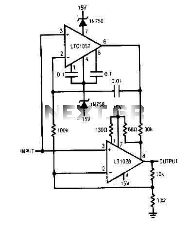
It uses the LT1052 and LT1028. The power supply should be dual with ±15V at 500mA. This is an ideal stabilized amplifier. The circuit utilizes the LT1052 and LT1028 operational amplifiers, which are known for their precision and stability. The...
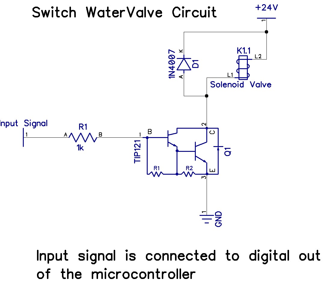
The Arduino Uno has adequate memory and ports, but efficient programming is necessary to store settings in memory. The Mega version offers increased memory and ports. The Shako valve operates on 24 volts DC; however, 12 volts is preferred...
The figures below illustrate using opamps as active 2nd order filters. Three 2nd order filters are shown, low pass, high pass, and bandpass. Each of these filters will attenuate frequencies outside their passband at a rate of 12dB per...
This is a schematic diagram of a stereo audio amplifier for a car. The circuit is powered by a single IC, the TDA1553, along with some external components. This IC is designed to manage the stereo car audio system....
Do you long for a beach holiday on a tropical island, but you don't have the necessary means? There is a solution: build the i-TRIXX surf simulator, put on your headphones, and escape from this mundane reality. Allow the...