
Edge detector
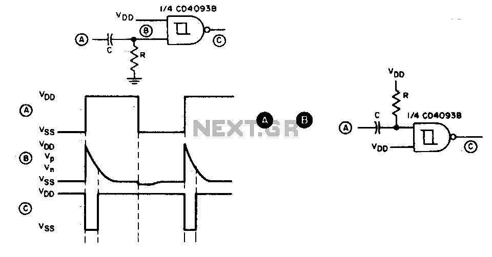
This circuit functions as a pulse generator that reacts specifically to the rising edges of an input waveform. The input signal is first coupled into the circuit via a capacitor, which serves to block any direct current (DC) components, allowing only the alternating current (AC) variations of the signal to pass through. Upon the occurrence of a positive-going edge, the capacitor momentarily charges, causing a rapid change in voltage across the output.
The output pulse's duration is critically dependent on the values of the resistor (R) and capacitor (C) in the circuit. The time constant, defined as τ = R × C, dictates how quickly the capacitor discharges after the initial charging. A larger resistor or capacitor will result in a longer pulse duration, while smaller values will produce shorter pulses. This behavior can be effectively modeled using the exponential discharge equation for the capacitor, which describes the voltage across the capacitor as it returns to its baseline value after the pulse.
For applications requiring detection of negative-going edges, an alternative circuit configuration as referenced in section B should be employed. This circuit would typically involve a different arrangement of components, such as using an inverting amplifier or a different capacitor placement, to ensure that the output pulse is generated in response to falling edges of the input signal. Such configurations can be tailored to meet specific timing and signal processing requirements in various electronic applications.This circuit provides a short negative-going output pulse for every positive-going edge at the input. The input waveform is coupled to the input by capacitor C; the pulse length depends, as before, on R and C
If a negative going edge detector is required, the circuit in B should be used. 🔗 External reference
Related Circuits
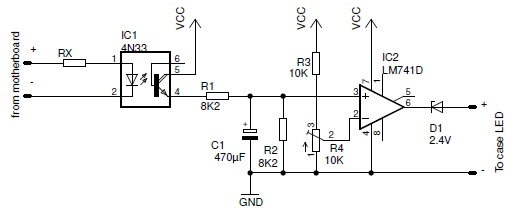
The PC Standby Detector is a compact circuit designed to deactivate the power LED when the PC enters standby mode. The PC Standby Detector circuit functions by monitoring the power state of the computer. When the computer is in standby...
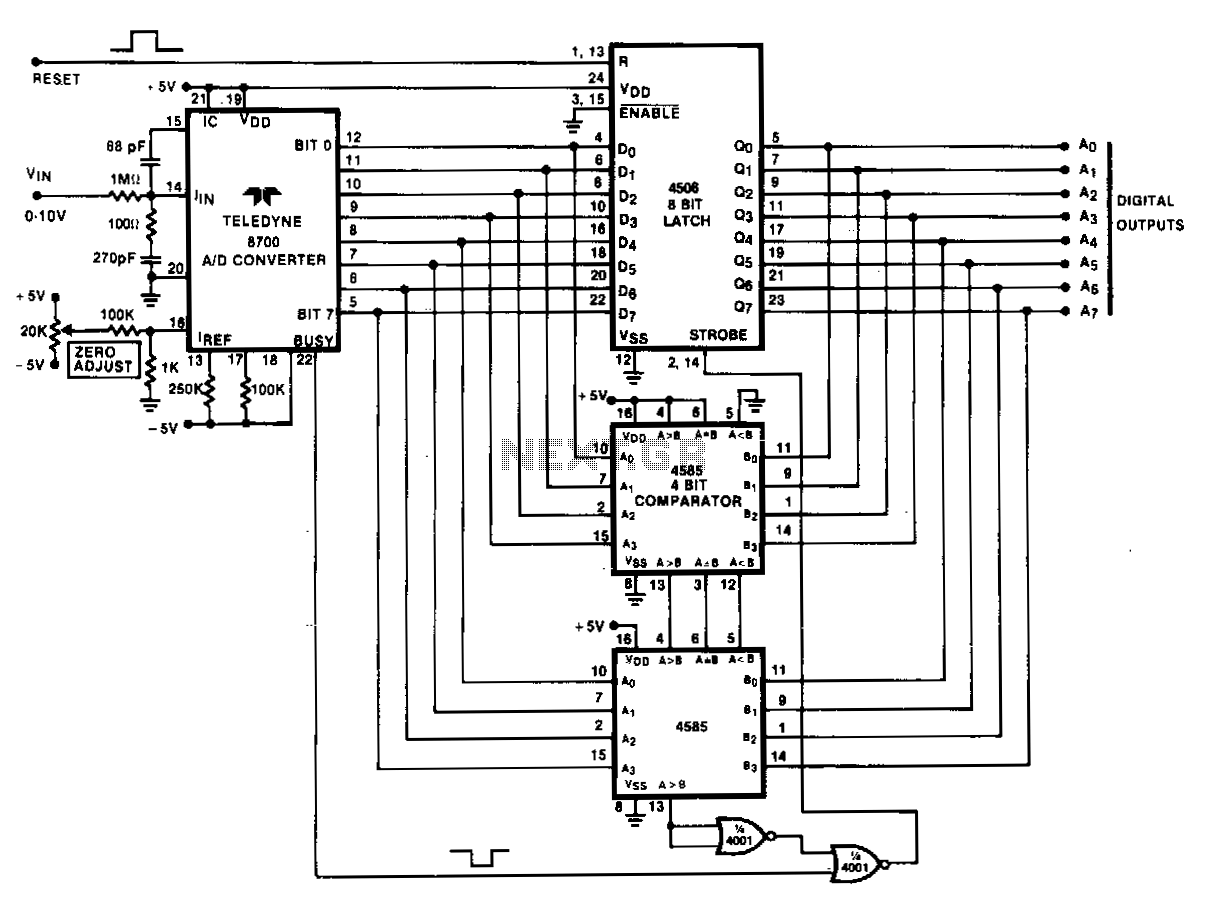
Analog peak detection is achieved by repeatedly measuring the input signal with an A/D converter and comparing the current reading with the previous reading. If the current reading is larger than the previous one, the current reading is stored...
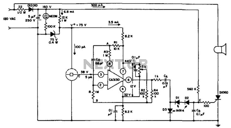
An ionization chamber in conjunction with a high-impedance CA3130 operational amplifier is utilized to detect the presence of smoke. When smoke is detected, the CA3130 ceases oscillation, which in turn triggers the S106D silicon-controlled rectifier (SCR) to sound an...
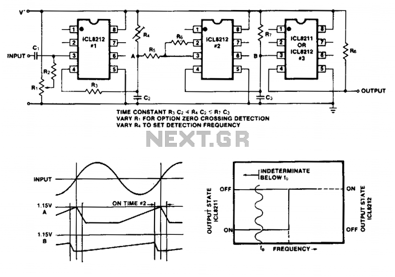
Simple frequency limit detectors providing a GO/NO-GO output for use with varying amplitude input signals may be conveniently implemented with the ICL8211/8212. In the application shown, the first ICL8212 is used as a zero-crossing detector. The output circuit consisting...
LED 1 will light and the buzzer turns on when the coil is changing inductance. The setup is easy, VR1 is adjusted (away from any metal objects) so that LED 1 will light and the buzzer sounds on, and...
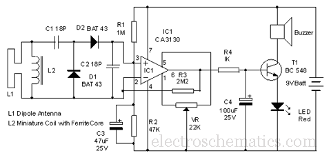
This circuit is designed to detect microwave sources, such as microwave ovens, satellite communication devices, and mobile phones. It provides audio-visual indications when microwaves in the gigahertz band are detected. Microwaves are a form of electromagnetic radiation with frequencies...
Warning: include(partials/cookie-banner.php): Failed to open stream: Permission denied in /var/www/html/nextgr/view-circuit.php on line 713
Warning: include(): Failed opening 'partials/cookie-banner.php' for inclusion (include_path='.:/usr/share/php') in /var/www/html/nextgr/view-circuit.php on line 713