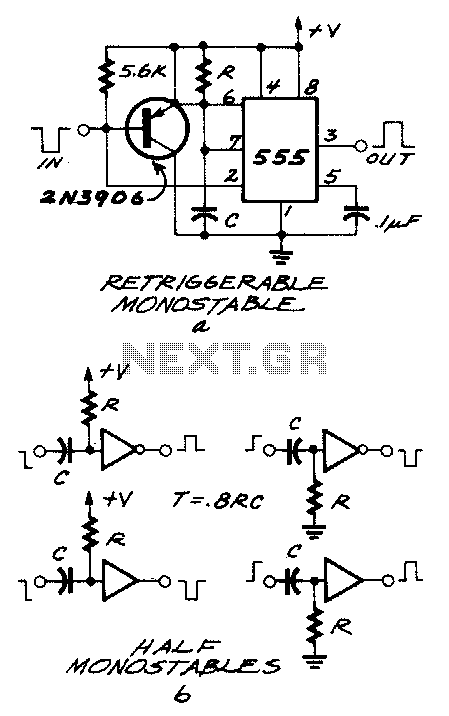
Edge-detector

The 555 timer is configured as a monostable multivibrator that requires a negative-going trigger. If the input pulse is positive-going, it can be inverted using an inverter circuit, which can be constructed with either an inverting gate or a single transistor if space is limited. Both configurations are illustrated. The circuits depicted are also edge detectors and are commonly referred to as half monostables, as they are not suitable for all applications. The duration of the output pulse is determined by the resistor-capacitor (RC) time constant, and there are several important guidelines for their operation: the input pulse must be longer than the output pulse, the input pulse should be free of glitches, and the circuit cannot be retriggered faster than the RC time constant allows.
The 555 timer in monostable mode operates by generating a single output pulse in response to a triggering input. Upon receiving a negative-going pulse, the output switches from low to high for a time period determined by the RC network connected to the timing pin. The timing capacitor charges through the resistor until it reaches approximately 2/3 of the supply voltage, at which point the output returns to low.
To accommodate a positive-going input pulse, an inverter is necessary. This inverter can be implemented using a logic gate or a transistor, which will convert the positive pulse to a negative pulse suitable for triggering the 555 timer. The choice of inverter will depend on space constraints and specific application requirements.
The design of the RC timing network is critical, as it sets the duration of the output pulse. The resistor (R) and capacitor (C) values must be selected carefully to ensure that the output pulse is shorter than the input pulse. Additionally, to prevent erroneous triggering, the input pulse must be stable and free from noise or glitches. The timing circuit should not be retriggered more frequently than the time it takes for the capacitor to charge, which is dictated by the RC time constant.
Overall, this configuration is useful for applications requiring pulse width modulation, signal conditioning, or event timing, while adhering to the operational constraints outlined.The 555 is a monostable that wants a negativegoing trigger. If the pulse you"re feeding it with is positive-going, you can run it through an inverter made up of either an inverting gate or, if you"re tight on space, a single transistor. Both ways are shown. The circuits shown in Fig. 25-9b are edge detectors as well, and are usually referred to as half monostables, since they can"t be used in every application.
The width of the output pulse is determined by the RC value, but there are a few rules governing their use: The input pulse has to be wider than the output pulse. The input pulse can"t be glitchy. The circuit can"t be retriggered faster than the RC time.