
Effective Load Resistance
The evaluation of power supplies typically hinges on their efficiency during the power conversion process. This metric is often quantified using established equations that calculate conversion efficiency, which is a critical factor in assessing the performance of DC-DC converters. However, the reliance on efficiency alone can obscure the true performance characteristics of converters, particularly when output conditions vary. The proposed method, which introduces the Effective Loss Resistance (Rol), aims to provide a more nuanced understanding of converter performance that is less influenced by changes in output voltage.
In conventional scenarios, efficiency is a straightforward metric for comparison, especially when input and output voltages are stable. However, the article emphasizes that efficiency can yield misleading results when comparing converters under different output conditions. For instance, while power loss remains relatively constant across varying output voltages, the efficiency figures can fluctuate significantly, leading to an inaccurate representation of a converter's performance.
The article further categorizes loss mechanisms in DC-DC converters into two primary types: conduction (Ohmic) losses and dynamic (switching) losses. Conduction losses arise from the on-resistance of MOSFETs and are primarily dependent on the load current squared, demonstrating a quadratic relationship. Meanwhile, dynamic losses are influenced by the input voltage and the converter's switching frequency, with rise and fall times also playing a role. Notably, these losses are only secondarily affected by output voltage, indicating that the fundamental loss characteristics remain relatively stable across various output conditions.
The findings illustrate that as output voltage decreases while maintaining a constant load current, the efficiency of the converter diminishes. This relationship complicates direct comparisons between converters operating at different output voltages. The graphical representation in the article further elucidates this point, showing that efficiency at a lower output voltage can appear disproportionately low compared to higher output voltages, despite power dissipation being nearly constant.
In conclusion, the introduction of the Effective Loss Resistance (Rol) offers a more reliable framework for evaluating DC-DC converters, enabling engineers to assess performance without the confounding effects of fluctuating output voltage. This method enhances the understanding of power supply performance and aids in the design and selection of converters for specific applications.This article offers an alternative to efficiency measurements as an evaluation tool of power supplies. The proposed method works well with little dependency on the output voltage and temperature. Power supplies have always been evaluated and compared based on the how efficient the conversion process is.
Equations 1 and 2 are two of the most used f ormulae to calculate the power conversion efficiency ·. The use of efficiency as a yardstick to evaluate DC-DC converters represents a very simple and in most cases effective way of comparison. Efficiency figure combined with the details of the converter parameters also allows the thermal engineer to calculate the thermal load of the converter and whether heatsink and/or cooling airflow is required.
The efficiency tool works very well when we have established standard input and output voltages that are more or less fixed in value. We will show that the efficiency alone is not the right tool to compare converters operating at different output conditions even with a fixed input voltage and switching frequency.
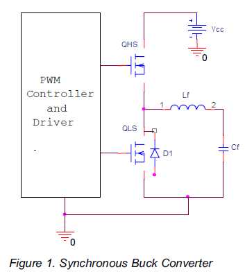
We will explain why that is and propose an alternative methods that measures the performance almost independent of the output voltage that gives a much more accurate and unambiguous idea about the converter`s performance so we introduce the concept of the Effective Loss Resistance, Rol. Figure 1 depicts a simplified block diagram of a synchronous buck converter used in the evaluation of this paper.
It is worthwhile mentioning that this work may be adapted to almost all DC-DC converters. Figure 2 shows the efficiency of a given converter at different output voltages. Although the power loss is mainly dependant on the load current at a fixed switching frequency and input voltage and is very lightly dependant on the output voltage within the range from 2V to 1V i. e. we have almost constant power loss in all of the out voltage conditions while the efficiency varies dramatically.
So even though the power loss is almost a constant, the very fact that we have a smaller output voltage will result in non realistic smaller efficiency figure. Loss mechanisms in DC-DC converters can be divided into two major groups as follows: Conduction or Ohmic losses.
Thisis the loss due to Iload2 x RDS(ON) x ” where RDS(ON) is the on-resistance of the MOSFET, Iload is the load current and ” is the duty cycle. Please note that this loss mechanism is mainly dependant on Iload2 because of the quadratic relationship and to a lesser degree on the output voltage since ” is a function of the output voltage that is topology dependant.
Dynamic or switching losses = Iload x Vin x ½ x fs x (tr+tf) where Vin is the input voltage and tr & tf are the rise and fall times and fs is the converter`s switching frequency. Again you can see that the dynamic losses are not dependant on the output voltage. This means that the losses are dependant on the output voltage in a secondary way. This leads immediately to the conclusion that we have more or less fixed losses regardless of the output voltage.
Why is this important Because as can be seen in the efficiency equation (2) above, the smaller the output voltage the smaller the output power for the same output current. This results a lower efficiency for smaller output voltage as can clearly be seen in Figure 2. One can see that there is a limiting condition as the output voltage goes to zero while maintaining the same output current at which point the efficiency is theoretically zero: That is to say that the efficiency of a given converter is proportional to the output voltage for the same load current.
This fact makes the comparison very difficult under different conditions of output voltage. Figure 2 depicts this very case where you can see that the efficiency at an output voltage of 2 volts is about 8% larger than that at 1V output at the same load current though the power dissipation is almost the same 🔗 External reference
Related Circuits
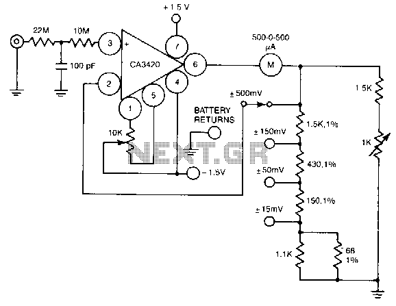
A resistance of 1,000,000 MΩ takes advantage of the high input impedance of the CA3420 BiMOS op-amp. Only two 1.5-V AA-type penlite batteries are required for use. Full-scale deflection is ±500 nV, ±150 mV, and ±15 mV. The circuit utilizes...
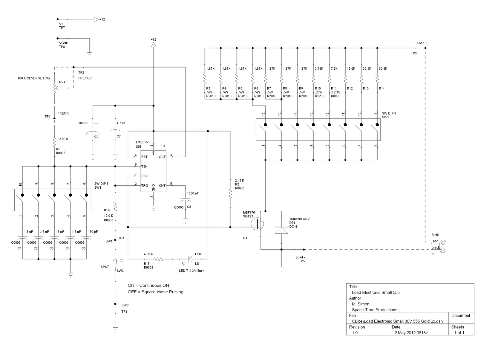
This is a license to use the files to manufacture up to 12 boards. If additional boards are required, please make contact. It is important to note that the order must specify the intent to produce 12 or fewer...
The current feedback operational amplifier maintains a consistent bandwidth even when the open-loop gain is altered. This characteristic makes it particularly suitable for applications in video signal amplification and the driving circuits of video cables. The accompanying diagram illustrates...
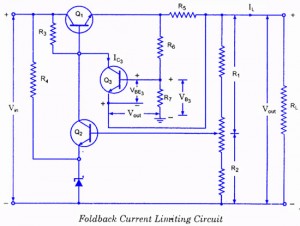
If the load resistance (RL) is reduced or the load terminals are accidentally shorted, a very large load current will flow, potentially damaging the pass transistor (Q1), diode, or other components. Fuse protection may not be sufficient, as the...

Most analog multimeters can measure resistance across a wide range of values; however, they can be inconvenient due to their reverse reading scale, which is also non-linear. This can lead to poor accuracy, especially at the high-value end of...
As circuit power supply voltages decrease and green energy trends gain popularity, designers should re-evaluate circuits that continuously consume power to reduce overall system power consumption. One such circuit is the "normally-ON" circuit, which can now be redesigned with...