
Efficient inverter control circuit
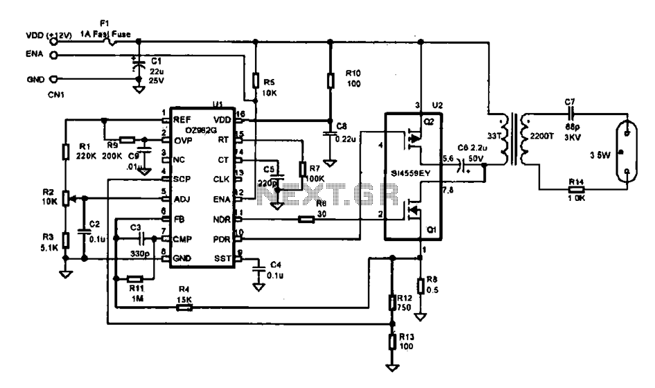
The efficient inverter control circuit described operates as a critical component in providing power to LCD backlight systems. The circuit architecture begins with a +1V DC input, which is filtered through capacitor C1 to ensure a stable voltage supply for the UL (02962G) integrated circuit. This IC serves as the control unit, utilizing a start signal (ENA) to enable or disable the inverter circuit based on operational requirements.
The driving field-effect transistor (U2) plays a vital role in modulating the power delivered to the step-up transformer. When the inverter is activated by the ENA signal, the UL chip produces a pulse-width modulation (PWM) signal at its output pin. This PWM signal controls the switching of the field-effect transistor, allowing it to efficiently manage the energy transfer to the transformer.
The step-up transformer is designed to amplify the voltage generated by the field-effect transistor to approximately 800V. This high voltage is essential for powering the backlight lamp, which illuminates the LCD display. The configuration of the transformer and the associated circuitry is optimized to ensure minimal losses and high efficiency in the energy conversion process.
Overall, this inverter control circuit is engineered to provide reliable and effective power management for LCD backlighting applications, ensuring that the display operates at optimal brightness levels while maintaining energy efficiency.Efficient inverter control circuit It shows a highly efficient inverter control circuit, which is used as the LCD backlight power supply circuit, which is mainly controlled by the chip Ul (02962G), the driving field effect transistor U2, Dan-voltage transformer, the backlight lamp and associated circuitry configuration. After the DC power sent by the +1V DC voltage through the filter capacitor Cl integrated circuit Ul and driving power field-effect transistor; start signal (ENA) will be sent to the U1 feet for controlling the inverter circuit opens, stop.
When the inverter power supply is normal, after receiving the start signal from the Ul of ? foot guard pin output PWM pulse signal interaction, after driving into the field effect transistor amplifier in step-up transformer, the pulse from the step-up transformer voltage up to about 800 V, power supply for the backlight lamp.
Related Circuits
A unit that is often very useful for isolating two stages in sound circuits. This circuit incorporates an amplification unit with a gain of X1. It employs only local negative feedback rather than total negative feedback, resulting in very...
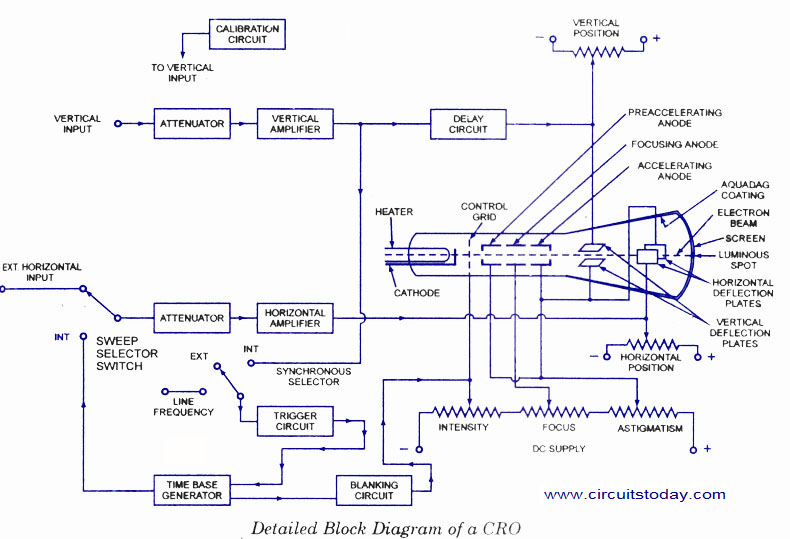
The number of controls required on a panel of a Cathode Ray Oscilloscope (CRO) is essential for its proper functioning. Intensity control is provided to adjust the brightness of the spot on the screen by varying the voltage between...
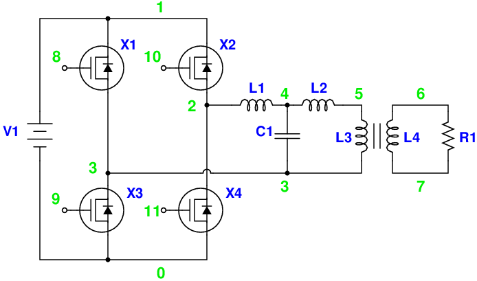
Magic Sinewave Analysis using SPICE and a Simple Inverter Circuit. This document discusses the analysis of a sinewave signal generated by a simple inverter circuit using SPICE simulation software. The inverter circuit is designed to convert a DC input voltage...
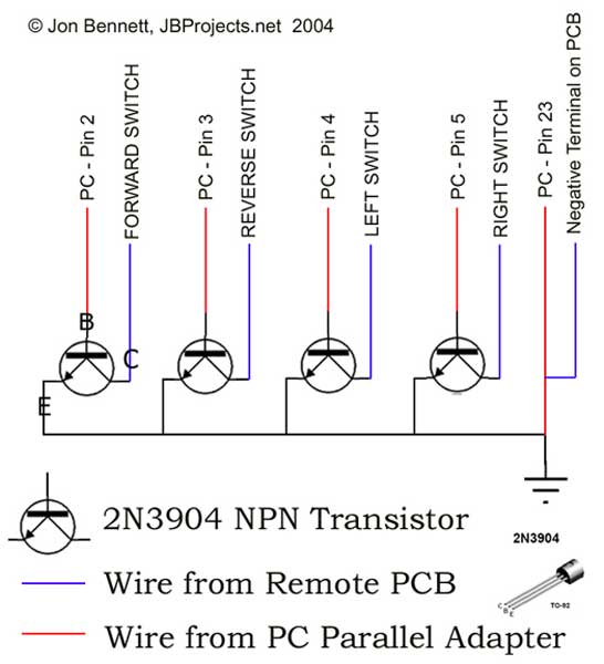
This project article was originally written in 2004 when most computers had parallel ports. This is no longer the case, so much of this information is now outdated. The Mini RC Car Project has been one of the most...

The PGA202 offset voltage correction circuit is designed to correct both input and output offset voltages. There are four different gain settings for the PGA202, which result in slight variations in input offset voltage. A 50k potentiometer is used...
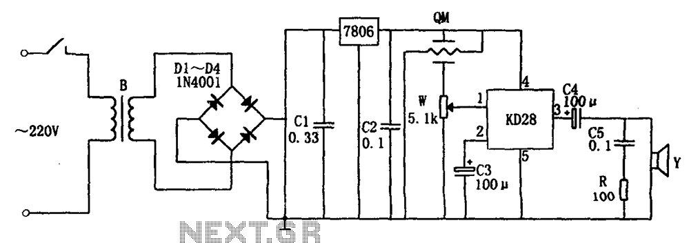
The system includes a gas-sensitive sensor element QM (type QM-N5), a buck rectifier, and regulator circuits, integrated circuits KD28, a speaker Y, and other components. The buck regulator circuit features a transformer rectifier and a bridge rectifier comprising diodes...