Electromechanical Relays
1. Definition and Working Principle
1.1 Definition and Working Principle
Electromechanical relays serve as crucial components in various electrical systems, providing a versatile means of controlling circuits through the actuation of mechanical contacts. Understanding the fundamental operation of these relays is essential for engineers, physicists, and researchers working with automation, power systems, and control applications. ### Working Principle of Electromechanical Relays An electromechanical relay consists of an electromagnetic coil, a set of movable contacts, and stationary contacts. When a current passes through the coil, it generates a magnetic field, causing the movable contacts to either open or close, thus altering the circuit's state. This change in contact position enables the relay to control the flow of current in connected circuits based on external conditions. ### Key Operational Concepts - Coil Excitation: Applying a voltage to the relay coil generates a magnetic field that attracts the movable contacts. - Contact Action: The movement of contacts leads to the opening or closing of the circuit, depending on the relay type. - Contact Materials: Choices of materials for contacts affect the relay's ability to handle various currents and voltages. - Contact Arrangements: Relays can feature normally open (NO), normally closed (NC), or changeover contacts for different control scenarios. ### Real-world Applications Power Systems Protection: Electromechanical relays are used for overcurrent protection, voltage monitoring, and fault detection in electrical grids. Industrial Automation: Relays play a role in controlling motors, lighting systems, and sensors in manufacturing processes. Telecommunications: They facilitate signal routing and switching operations in complex communication networks. Automotive Electronics: Relays are vital for managing power distribution and circuit protection in vehicles. ### Historical Context The development of electromechanical relays dates back to the early 19th century, with significant advancements in materials, design, and functionality over the years. From telegraphy to modern automation, relays have been instrumental in the evolution of electrical engineering and control systems. ### Mathematical Representation The operational behavior of electromechanical relays can be mathematically described using principles of electromagnetic induction and circuit theory. The relay's response to input signals, coil current, and contact impedance can be modeled to predict its performance in different applications.1.1 Definition and Working Principle
Electromechanical relays serve as crucial components in various electrical systems, providing a versatile means of controlling circuits through the actuation of mechanical contacts. Understanding the fundamental operation of these relays is essential for engineers, physicists, and researchers working with automation, power systems, and control applications. ### Working Principle of Electromechanical Relays An electromechanical relay consists of an electromagnetic coil, a set of movable contacts, and stationary contacts. When a current passes through the coil, it generates a magnetic field, causing the movable contacts to either open or close, thus altering the circuit's state. This change in contact position enables the relay to control the flow of current in connected circuits based on external conditions. ### Key Operational Concepts - Coil Excitation: Applying a voltage to the relay coil generates a magnetic field that attracts the movable contacts. - Contact Action: The movement of contacts leads to the opening or closing of the circuit, depending on the relay type. - Contact Materials: Choices of materials for contacts affect the relay's ability to handle various currents and voltages. - Contact Arrangements: Relays can feature normally open (NO), normally closed (NC), or changeover contacts for different control scenarios. ### Real-world Applications Power Systems Protection: Electromechanical relays are used for overcurrent protection, voltage monitoring, and fault detection in electrical grids. Industrial Automation: Relays play a role in controlling motors, lighting systems, and sensors in manufacturing processes. Telecommunications: They facilitate signal routing and switching operations in complex communication networks. Automotive Electronics: Relays are vital for managing power distribution and circuit protection in vehicles. ### Historical Context The development of electromechanical relays dates back to the early 19th century, with significant advancements in materials, design, and functionality over the years. From telegraphy to modern automation, relays have been instrumental in the evolution of electrical engineering and control systems. ### Mathematical Representation The operational behavior of electromechanical relays can be mathematically described using principles of electromagnetic induction and circuit theory. The relay's response to input signals, coil current, and contact impedance can be modeled to predict its performance in different applications.Key Components of Electromechanical Relays
Electromechanical relays are intricate devices that serve as crucial components in various electrical systems. Understanding the key elements within a relay is fundamental to grasping their functionality and applications. Let's delve into the essential components that make up an electromechanical relay: ### Armature The armature is a pivotal component within an electromechanical relay that moves in response to the coil's electromagnetic field. This movement either completes or breaks the electrical circuit, facilitating the switching action of the relay. ### Coil The coil, often made of copper wire, generates a magnetic field when an electric current flows through it. This magnetic field attracts the armature, initiating the mechanical switching operation of the relay. ### Contact Mechanism The contact mechanism consists of stationary and movable contacts. When the relay is energized, the movable contact, connected to the armature, moves to establish or disrupt the connection with the stationary contact. This mechanism enables the relay to control the flow of current within a circuit. ### Spring The spring in an electromechanical relay plays a crucial role in providing the necessary force to return the armature to its original position when the coil is de-energized. This action ensures the reliable and rapid operation of the relay. ### Yoke The yoke serves as a support structure for the armature and the coil, maintaining their alignment and providing stability during the relay's operation. It helps optimize the relay's efficiency and longevity. ### Enclosure The enclosure of an electromechanical relay serves the dual purpose of protecting the internal components from environmental factors and ensuring user safety by insulating the high voltage components. By understanding the functions and interactions of these key components, engineers and researchers can effectively design and deploy electromechanical relays in various applications, ranging from industrial control systems to telecommunications infrastructure. --- Utilizing these intricate components, electromechanical relays cater to a multitude of industries, including automation, power distribution, and telecommunications. Their versatility and reliability make them indispensable in modern electrical systems, where precise control and switching functions are required.Key Components of Electromechanical Relays
Electromechanical relays are intricate devices that serve as crucial components in various electrical systems. Understanding the key elements within a relay is fundamental to grasping their functionality and applications. Let's delve into the essential components that make up an electromechanical relay: ### Armature The armature is a pivotal component within an electromechanical relay that moves in response to the coil's electromagnetic field. This movement either completes or breaks the electrical circuit, facilitating the switching action of the relay. ### Coil The coil, often made of copper wire, generates a magnetic field when an electric current flows through it. This magnetic field attracts the armature, initiating the mechanical switching operation of the relay. ### Contact Mechanism The contact mechanism consists of stationary and movable contacts. When the relay is energized, the movable contact, connected to the armature, moves to establish or disrupt the connection with the stationary contact. This mechanism enables the relay to control the flow of current within a circuit. ### Spring The spring in an electromechanical relay plays a crucial role in providing the necessary force to return the armature to its original position when the coil is de-energized. This action ensures the reliable and rapid operation of the relay. ### Yoke The yoke serves as a support structure for the armature and the coil, maintaining their alignment and providing stability during the relay's operation. It helps optimize the relay's efficiency and longevity. ### Enclosure The enclosure of an electromechanical relay serves the dual purpose of protecting the internal components from environmental factors and ensuring user safety by insulating the high voltage components. By understanding the functions and interactions of these key components, engineers and researchers can effectively design and deploy electromechanical relays in various applications, ranging from industrial control systems to telecommunications infrastructure. --- Utilizing these intricate components, electromechanical relays cater to a multitude of industries, including automation, power distribution, and telecommunications. Their versatility and reliability make them indispensable in modern electrical systems, where precise control and switching functions are required.Types of Electromechanical Relays
Electromechanical relays come in various types, each tailored for specific applications based on their design, contact configuration, and operation principles. ####Solid-State Relays
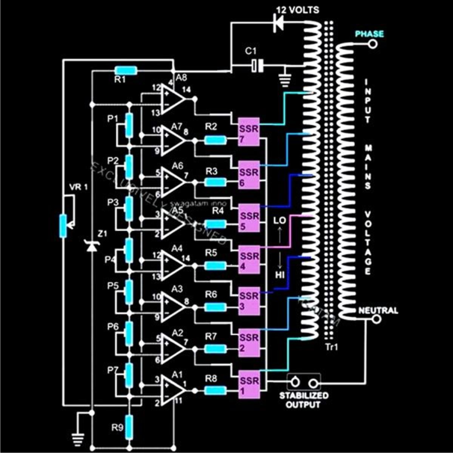
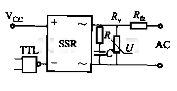
Solid-state relays (SSRs) have no moving parts, relying on semiconductor devices for switching. They offer faster response times, longer lifespan, and vibration resistance compared to traditional relays. SSRs find extensive use in applications requiring precise control and high switching frequencies, such as in industrial automation, robotics, and temperature control systems. ####Latching Relays
Latching relays maintain their state even after power is removed, reducing power consumption in control circuits. These relays feature two stable states (set and reset) achieved through a mechanical or electronic mechanism. They are commonly used in energy-efficient control systems, memory backup applications, and telecommunications. ####Reed Relays
Reed relays utilize magnetic fields to control the switching action. These relays consist of reed switches enclosed within a glass tube filled with inert gas, ensuring reliable and low-level signal switching. Reed relays are ideal for high-speed and low-level signal applications in communication systems, automated test equipment, and medical devices. ####Magnetic Latching Relays
Magnetic latching relays use permanent magnets to maintain their state, offering energy-efficient operation and reduced heat dissipation. These relays are suitable for power-critical applications where maintaining the last state during power loss is vital, such as in smart meters, energy management systems, and automotive electronics. ####Overload Protection Relays
Overload protection relays detect abnormal current levels and disconnect the circuit to prevent damage to equipment. These relays safeguard motors, transformers, and other electrical devices from overheating and electrical faults. They are essential components in electrical distribution systems, motor control centers, and industrial machinery. By understanding the characteristics and functionalities of these different types of electromechanical relays, engineers and researchers can select the most suitable relay for their specific application requirements. Each type offers unique advantages and capabilities that cater to diverse industrial and commercial needs.Types of Electromechanical Relays
Electromechanical relays come in various types, each tailored for specific applications based on their design, contact configuration, and operation principles. ####Solid-State Relays
Solid-state relays (SSRs) have no moving parts, relying on semiconductor devices for switching. They offer faster response times, longer lifespan, and vibration resistance compared to traditional relays. SSRs find extensive use in applications requiring precise control and high switching frequencies, such as in industrial automation, robotics, and temperature control systems. ####Latching Relays
Latching relays maintain their state even after power is removed, reducing power consumption in control circuits. These relays feature two stable states (set and reset) achieved through a mechanical or electronic mechanism. They are commonly used in energy-efficient control systems, memory backup applications, and telecommunications. ####Reed Relays
Reed relays utilize magnetic fields to control the switching action. These relays consist of reed switches enclosed within a glass tube filled with inert gas, ensuring reliable and low-level signal switching. Reed relays are ideal for high-speed and low-level signal applications in communication systems, automated test equipment, and medical devices. ####Magnetic Latching Relays
Magnetic latching relays use permanent magnets to maintain their state, offering energy-efficient operation and reduced heat dissipation. These relays are suitable for power-critical applications where maintaining the last state during power loss is vital, such as in smart meters, energy management systems, and automotive electronics. ####Overload Protection Relays
Overload protection relays detect abnormal current levels and disconnect the circuit to prevent damage to equipment. These relays safeguard motors, transformers, and other electrical devices from overheating and electrical faults. They are essential components in electrical distribution systems, motor control centers, and industrial machinery. By understanding the characteristics and functionalities of these different types of electromechanical relays, engineers and researchers can select the most suitable relay for their specific application requirements. Each type offers unique advantages and capabilities that cater to diverse industrial and commercial needs.2. Industrial Automation
2.1 Industrial Automation
Welcome to the realm where electromechanical relays play a pivotal role in enhancing industrial automation processes. In this section, we delve into the intricate workings of these devices and explore their applications in automation systems.
The Principle of Electromechanical Relays
At the heart of industrial automation lie electromechanical relays, devices that bridge the gap between electrical and mechanical systems. These relays operate on the principle of electromagnetic attraction, where a coil carrying a current generates a magnetic field that actuates a set of contacts.
This electromagnetic phenomenon allows for the seamless switching of electrical circuits within industrial automation setups, offering precise control and monitoring capabilities.
Application in Programmable Logic Controllers (PLCs)
Programmable Logic Controllers (PLCs) form the backbone of modern industrial automation systems. Electromechanical relays play a crucial role in PLCs, enabling the routing of signals, monitoring of sensors, and controlling actuators based on predefined logic.
By integrating electromechanical relays into PLC systems, engineers can design versatile and efficient automation solutions for a wide range of industrial processes, boosting productivity and safety simultaneously.
Real-World Integration
The practical application of electromechanical relays in industrial automation extends to various sectors, including manufacturing, energy, automotive, and more. These devices facilitate the seamless coordination of machinery, ensuring smooth operations and adherence to predefined control sequences.
Moreover, the reliability and durability of electromechanical relays make them indispensable components in critical industrial processes, where precision and safety are paramount.
2.2 Automotive Systems
In automotive systems, electromechanical relays play a crucial role in controlling various components like lights, motors, and other electrical systems in vehicles. These relays are designed to withstand the rigors of vehicle environments, including temperature fluctuations, vibrations, and high currents.
Automotive relays are often used in circuits that involve controlling high-power devices such as headlights, cooling fans, and fuel pumps. They offer a reliable switching mechanism that can handle the demands of automotive applications.
One common application of electromechanical relays in automotive systems is in the control of the high-beam and low-beam headlights. When the driver switches between the two modes, the relay toggles between the circuits, allowing the appropriate lights to turn on or off.
Additionally, relays are used in automotive starter systems to connect the battery to the starter motor when the ignition key is turned. This ensures a reliable and safe start for the vehicle by handling the high currents required during the cranking process.
2.3 Home Appliances
In the realm of home appliances, electromechanical relays play a crucial role in controlling various devices. From washing machines to microwave ovens, these relays are responsible for switching the power supply on and off based on specific conditions.
Understanding the intricate workings of electromechanical relays is essential for ensuring the safety and efficiency of these appliances. Let's delve deeper into how these relays function in different household devices and the importance of their design and implementation.
3. Voltage and Current Ratings
3.1 Voltage and Current Ratings
In electromechanical relays, voltage and current ratings play a crucial role in determining the operational limits and reliability of the relay. These ratings are key specifications that engineers need to consider when selecting a relay for a specific application.
Voltage Ratings:
When discussing voltage ratings, we are primarily concerned with two key parameters: contact voltage rating and coil voltage rating.
Contact Voltage Rating:
The contact voltage rating refers to the maximum voltage that the relay contacts can safely switch or carry. Exceeding this rating can lead to arcing, contact welding, and insulation breakdown.
For example, a relay with a contact voltage rating of 250V AC is suitable for switching loads up to 250V AC. It is crucial to choose a relay with a contact voltage rating higher than the maximum voltage of the circuit to ensure safe and reliable operation.
Coil Voltage Rating:
The coil voltage rating specifies the voltage required to energize the relay coil and activate the switch contacts. It is essential to apply the correct coil voltage to ensure proper operation of the relay.
For instance, a relay with a coil voltage rating of 12V DC requires a 12V DC power supply to energize the coil and initiate the switching action.
Current Ratings:
Similar to voltage ratings, current ratings in relays are divided into contact current rating and coil current rating.
Contact Current Rating:
The contact current rating specifies the maximum current that the relay contacts can carry without experiencing excessive heat generation or damage. It is crucial to select a relay with a contact current rating higher than the maximum current in the circuit to prevent relay failure.
For example, a relay with a contact current rating of 10A can safely switch loads up to 10A without overheating or degrading the contacts.
Coil Current Rating:
The coil current rating determines the current consumption of the relay coil when energized. Understanding this rating is essential for properly sizing the power supply driving the relay and preventing coil overheating.
For instance, a relay with a coil current rating of 50mA requires a power supply capable of delivering at least 50mA to energize the coil effectively.
Understanding the voltage and current ratings of electromechanical relays is essential for designing reliable circuits and ensuring safe operation in various applications. Engineers must carefully evaluate these specifications to select the most suitable relay for a specific task.
Contact Configuration and Ratings
When it comes to electromechanical relays, contact configurations and ratings play a critical role in determining the performance and application suitability of the relay. In this section, we will delve into the intricacies of contact configurations and ratings.
Contact Configuration
Electromechanical relays are characterized by different contact configurations, including:
- Single-Pole Single-Throw (SPST): This configuration has a single set of contacts that are either open or closed.
- Single-Pole Double-Throw (SPDT): With one pole and two possible output states, this configuration is versatile for applications requiring switching between two circuits.
- Double-Pole Single-Throw (DPST): Featuring two sets of contacts that act simultaneously, this configuration is useful for applications requiring a shared connection.
- Double-Pole Double-Throw (DPDT): Offering two poles and two possible output states per pole, this configuration is ideal for complex switching scenarios.
Understanding the contact configuration of a relay is crucial for ensuring compatibility with the intended circuit and achieving the desired functionality.
Contact Ratings
Relay contacts are rated based on various parameters that influence their performance and longevity:
- Current Rating: The maximum current the contacts can handle without sustaining damage.
- Voltage Rating: The maximum voltage that can be applied across the contacts without arcing or breakdown.
- Switching Capacity: The ability of the contacts to handle a specific power level during switching operations.
- Insulation Resistance: The resistance between open contacts to prevent leakage current.
- Operating Life: The expected number of switching cycles before the contacts degrade.
Proper consideration of contact ratings is essential to ensure reliable operation and prevent premature failure of the relay in practical applications.
Real-World Applications
The choice of contact configuration and ratings significantly impacts the suitability of a relay for diverse applications. For instance, in industrial automation, relays with high switching capacities and long operating lives are preferred for robust performance in demanding environments. On the other hand, in low-power control circuits, relays with specific current and voltage ratings are selected to ensure safe and efficient operation.
Switching Speed and Response Time
Advanced understanding of the electromagnetic interactions in electromechanical relays leads to insights into their switching speed and response time. These characteristics are crucial in various applications where rapid and precise switching is required. In electromechanical relays, the switching speed and response time are influenced by several factors, including the coil design, contact materials, and mechanical configurations. The time required for the relay to transition from one state to another directly impacts its operational efficiency and overall performance. ### Factors Affecting Switching Speed and Response Time The speed at which an electromechanical relay can switch from one state to another depends on the following key factors: 1. Coil Characteristics: The inductance of the coil and the applied voltage determine the magnetic field strength, affecting the speed of the mechanical contacts. 2. Contact Materials: The material composition of the contact points directly impacts the friction, wear, and electrical resistance during switching, thus influencing the speed and response time. 3. Mechanical Design: The physical structure, including the contact arrangement, spring tension, and armature geometry, plays a vital role in determining how quickly the contacts can open or close. ### Mathematical Analysis To quantify the switching speed and response time of an electromechanical relay, it is essential to model the system's dynamics mathematically. By analyzing the electrical and mechanical characteristics of the relay, it is possible to derive expressions that describe the time constants and response behavior. Let's consider a simple model where the relay undergoes an electrical input that triggers a mechanical response. By applying principles of circuit theory and mechanical dynamics, we can formulate equations that relate the input signal to the time it takes for the relay to fully switch states. ### Practical Applications The knowledge of switching speed and response time is crucial in various applications, such as industrial automation, power distribution systems, and telecommunications. Understanding the relay's dynamic behavior allows engineers to optimize system performance, reduce electromagnetic interference, and enhance reliability. ### Conclusion In conclusion, the switching speed and response time of electromechanical relays are fundamental aspects that impact their overall functionality and application suitability. By delving into the intricate interplay between electromagnetic forces, mechanical components, and electrical characteristics, it is possible to design and operate relays effectively in diverse settings.Switching Speed and Response Time
Advanced understanding of the electromagnetic interactions in electromechanical relays leads to insights into their switching speed and response time. These characteristics are crucial in various applications where rapid and precise switching is required. In electromechanical relays, the switching speed and response time are influenced by several factors, including the coil design, contact materials, and mechanical configurations. The time required for the relay to transition from one state to another directly impacts its operational efficiency and overall performance. ### Factors Affecting Switching Speed and Response Time The speed at which an electromechanical relay can switch from one state to another depends on the following key factors: 1. Coil Characteristics: The inductance of the coil and the applied voltage determine the magnetic field strength, affecting the speed of the mechanical contacts. 2. Contact Materials: The material composition of the contact points directly impacts the friction, wear, and electrical resistance during switching, thus influencing the speed and response time. 3. Mechanical Design: The physical structure, including the contact arrangement, spring tension, and armature geometry, plays a vital role in determining how quickly the contacts can open or close. ### Mathematical Analysis To quantify the switching speed and response time of an electromechanical relay, it is essential to model the system's dynamics mathematically. By analyzing the electrical and mechanical characteristics of the relay, it is possible to derive expressions that describe the time constants and response behavior. Let's consider a simple model where the relay undergoes an electrical input that triggers a mechanical response. By applying principles of circuit theory and mechanical dynamics, we can formulate equations that relate the input signal to the time it takes for the relay to fully switch states. ### Practical Applications The knowledge of switching speed and response time is crucial in various applications, such as industrial automation, power distribution systems, and telecommunications. Understanding the relay's dynamic behavior allows engineers to optimize system performance, reduce electromagnetic interference, and enhance reliability. ### Conclusion In conclusion, the switching speed and response time of electromechanical relays are fundamental aspects that impact their overall functionality and application suitability. By delving into the intricate interplay between electromagnetic forces, mechanical components, and electrical characteristics, it is possible to design and operate relays effectively in diverse settings.4. Basic Relay Circuit Design
4.1 Basic Relay Circuit Design
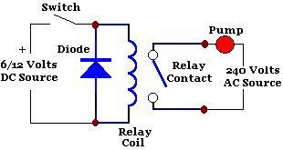
In the realm of electromechanical systems, relay circuits play a crucial role in controlling high-power electrical devices using low-power control signals. A relay is essentially an electrically operated switch, leveraging the principle of electromagnetic induction to open or close circuits. Let's delve into the fundamental aspects of designing relay circuits and explore their applications in advanced engineering scenarios. #### Electromagnetic Coil in Relay Circuits At the heart of a relay lies its electromagnetic coil. When a current passes through the coil, it generates a magnetic field, which in turn causes a mechanical armature to actuate, either opening or closing the relay contacts. This electromechanical action forms the basis of relay operation, enabling the isolation and control of electrical circuits. #### Understanding Relay Contacts Relays boast various contact configurations, including normally open (NO), normally closed (NC), and changeover contacts. NO contacts remain open in the resting state, closing upon relay activation. Conversely, NC contacts maintain continuity until energized, breaking the circuit upon activation. Changeover contacts offer the flexibility to switch between two separate circuits. #### Relay Coil Drive and Protection Efficient relay operation necessitates the careful consideration of coil drive mechanisms and protection circuits. Utilizing appropriate driving circuits, such as transistor drivers or solid-state relays, ensures stable and reliable coil activation. Moreover, incorporating flyback diodes safeguards sensitive components against voltage spikes induced during relay deactivation, enhancing system longevity. #### Practical Implementation and Applications In practical scenarios, relay circuits find widespread use in diverse applications such as industrial automation, power distribution systems, and automotive electronics. Leveraging relays enables the seamless integration of control logic into complex electromechanical systems, offering precise and robust switching capabilities for critical operations. #### Leveraging Advanced Relay Configurations Advanced relay configurations, including latching relays and time-delay relays, further augment the functionality and versatility of relay circuits. Latching relays retain their state without continuous power input, ideal for power-efficient applications. Time-delay relays introduce temporal control mechanisms, enabling precise timing operations in time-critical systems. #### Mathematical Modeling of Relay Dynamics To achieve meticulous control and optimization in relay circuits, mathematical modeling of relay dynamics proves invaluable. Deriving equations governing the transient response, contact bounce phenomena, and power dissipation characteristics facilitates in-depth analysis and performance enhancement of relay systems, empowering engineers to design robust and efficient relay-based solutions. This comprehensive exploration of basic relay circuit design sets the stage for delving deeper into the intricate realm of electromechanical systems. By understanding the principles governing relay operation, engineers and researchers can harness the full potential of relay technology in advancing modern electronics and automation domains.4.1 Basic Relay Circuit Design
In the realm of electromechanical systems, relay circuits play a crucial role in controlling high-power electrical devices using low-power control signals. A relay is essentially an electrically operated switch, leveraging the principle of electromagnetic induction to open or close circuits. Let's delve into the fundamental aspects of designing relay circuits and explore their applications in advanced engineering scenarios. #### Electromagnetic Coil in Relay Circuits At the heart of a relay lies its electromagnetic coil. When a current passes through the coil, it generates a magnetic field, which in turn causes a mechanical armature to actuate, either opening or closing the relay contacts. This electromechanical action forms the basis of relay operation, enabling the isolation and control of electrical circuits. #### Understanding Relay Contacts Relays boast various contact configurations, including normally open (NO), normally closed (NC), and changeover contacts. NO contacts remain open in the resting state, closing upon relay activation. Conversely, NC contacts maintain continuity until energized, breaking the circuit upon activation. Changeover contacts offer the flexibility to switch between two separate circuits. #### Relay Coil Drive and Protection Efficient relay operation necessitates the careful consideration of coil drive mechanisms and protection circuits. Utilizing appropriate driving circuits, such as transistor drivers or solid-state relays, ensures stable and reliable coil activation. Moreover, incorporating flyback diodes safeguards sensitive components against voltage spikes induced during relay deactivation, enhancing system longevity. #### Practical Implementation and Applications In practical scenarios, relay circuits find widespread use in diverse applications such as industrial automation, power distribution systems, and automotive electronics. Leveraging relays enables the seamless integration of control logic into complex electromechanical systems, offering precise and robust switching capabilities for critical operations. #### Leveraging Advanced Relay Configurations Advanced relay configurations, including latching relays and time-delay relays, further augment the functionality and versatility of relay circuits. Latching relays retain their state without continuous power input, ideal for power-efficient applications. Time-delay relays introduce temporal control mechanisms, enabling precise timing operations in time-critical systems. #### Mathematical Modeling of Relay Dynamics To achieve meticulous control and optimization in relay circuits, mathematical modeling of relay dynamics proves invaluable. Deriving equations governing the transient response, contact bounce phenomena, and power dissipation characteristics facilitates in-depth analysis and performance enhancement of relay systems, empowering engineers to design robust and efficient relay-based solutions. This comprehensive exploration of basic relay circuit design sets the stage for delving deeper into the intricate realm of electromechanical systems. By understanding the principles governing relay operation, engineers and researchers can harness the full potential of relay technology in advancing modern electronics and automation domains.4.2 Using Relays in Control Circuits
In this section, we will delve into the practical applications and intricacies of utilizing electromechanical relays in control circuits. Understanding how relays operate within a circuit is crucial for engineers designing complex systems. We will explore the key concepts and considerations when incorporating relays into control circuits.
Switching Mechanism and Operation
Electromechanical relays function as electrically operated switches and play a pivotal role in controlling the flow of current within a circuit. When a current passes through the relay coil, it generates a magnetic field that actuates the switch mechanism, allowing the relay contacts to change state. This switching action enables the control of higher voltage or current loads using a low-power signal.
Relay Contact Configurations
Relays come in various contact configurations, including:
- Normally Open (NO)
- Normally Closed (NC)
- Changeover (CO) or Single Pole Double Throw (SPDT)
Understanding these configurations is essential for determining how the relay will influence the circuit based on its state.
Applications in Control Circuits
Relays are extensively used in control circuits for a multitude of applications, such as:
- Automotive systems
- Industrial automation
- Home automation
- Robotics
The ability of relays to provide isolation and switching capabilities makes them indispensable in various control systems.
Advantages and Limitations
While relays offer several advantages like galvanic isolation and versatility, they also have limitations, including mechanical wear and limited switching speeds. Engineers need to consider these factors when designing control circuits to ensure optimal system performance.
Relay Timing and Protection
Timing considerations are crucial in applications where precise switching times are required. Additionally, implementing protective measures, such as flyback diodes to suppress voltage spikes or using snubber circuits, enhances the reliability and longevity of relays.
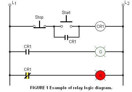
Case Study: Industrial Control System
Let's analyze a real-world scenario where electromechanical relays are integral to the functionality and safety of an industrial control system. By understanding the theoretical principles and practical implications, we can appreciate the significance of relays in complex control applications.
---By following these guidelines and insights, engineers and researchers can harness the full potential of electromechanical relays in designing sophisticated control circuits for diverse applications.
4.2 Using Relays in Control Circuits
In this section, we will delve into the practical applications and intricacies of utilizing electromechanical relays in control circuits. Understanding how relays operate within a circuit is crucial for engineers designing complex systems. We will explore the key concepts and considerations when incorporating relays into control circuits.
Switching Mechanism and Operation
Electromechanical relays function as electrically operated switches and play a pivotal role in controlling the flow of current within a circuit. When a current passes through the relay coil, it generates a magnetic field that actuates the switch mechanism, allowing the relay contacts to change state. This switching action enables the control of higher voltage or current loads using a low-power signal.
Relay Contact Configurations
Relays come in various contact configurations, including:
- Normally Open (NO)
- Normally Closed (NC)
- Changeover (CO) or Single Pole Double Throw (SPDT)
Understanding these configurations is essential for determining how the relay will influence the circuit based on its state.
Applications in Control Circuits
Relays are extensively used in control circuits for a multitude of applications, such as:
- Automotive systems
- Industrial automation
- Home automation
- Robotics
The ability of relays to provide isolation and switching capabilities makes them indispensable in various control systems.
Advantages and Limitations
While relays offer several advantages like galvanic isolation and versatility, they also have limitations, including mechanical wear and limited switching speeds. Engineers need to consider these factors when designing control circuits to ensure optimal system performance.
Relay Timing and Protection
Timing considerations are crucial in applications where precise switching times are required. Additionally, implementing protective measures, such as flyback diodes to suppress voltage spikes or using snubber circuits, enhances the reliability and longevity of relays.
Case Study: Industrial Control System
Let's analyze a real-world scenario where electromechanical relays are integral to the functionality and safety of an industrial control system. By understanding the theoretical principles and practical implications, we can appreciate the significance of relays in complex control applications.
---By following these guidelines and insights, engineers and researchers can harness the full potential of electromechanical relays in designing sophisticated control circuits for diverse applications.
Relay Protection and Safety Considerations
Electromechanical relays play a crucial role in various applications, but it is important to consider protection mechanisms and safety measures to ensure their reliable and safe operation. In this section, we delve into the key aspects of relay protection and safety considerations for advanced-level readers.
Overcurrent Protection
One of the fundamental protection mechanisms for relays is overcurrent protection. Overcurrent occurs when the current flowing through the relay exceeds its rated value, leading to potential damage. To safeguard against this, relays are equipped with protective elements such as thermal overload relays or fuses. These devices detect overcurrent conditions and interrupt the circuit to prevent overheating and damage.
Earth Fault Protection
Earth faults can pose a significant risk in electrical systems, especially when dealing with high voltage applications. To mitigate the impact of earth faults on relays, earth fault protection mechanisms are employed. These mechanisms detect the presence of earth faults and isolate the faulty section of the circuit to prevent further damage or electrical hazards.
Short Circuit Protection
Short circuits can cause a sudden surge of current, potentially damaging the relay and other components in the circuit. Relays are designed with short circuit protection features such as electromagnetic relays that can detect overcurrent conditions and quickly open the circuit to protect the system. Additionally, electronic relays may incorporate advanced circuitry to detect and respond to short circuit faults efficiently.
Thermal Protection
Thermal protection is essential to prevent relay components from overheating during prolonged operation or under high current conditions. By monitoring the temperature of the relay coil and contacts, thermal protection mechanisms can trigger a response when the temperature exceeds safe limits. This ensures the longevity and reliability of the relay in demanding operating environments.
Safety Considerations
In addition to protective measures, it is crucial to consider various safety aspects when working with relays. Proper insulation, grounding, and enclosure design are vital to prevent electrical shocks, fires, or other hazardous situations. Regular maintenance, inspection, and testing of relays are also essential to identify potential issues early and ensure optimal performance.
Understanding and implementing comprehensive relay protection and safety measures are critical in maintaining the integrity and reliability of electrical systems. By integrating these safeguards, engineers and researchers can enhance the performance and longevity of electromechanical relays in diverse applications.
5. Identifying Relay Failures
5.1 Identifying Relay Failures
Relays are essential components in electrical systems, serving as switches controlled by electrical signals. Identifying relay failures is critical to ensuring system reliability and performance.
When troubleshooting relays, it's crucial to understand common failure modes and their manifestations. Some typical relay failures include:
1. Contact Welding
Contact welding occurs when the relay contacts stick together due to excessive current or voltage, leading to a permanent closed circuit. This can result from overloading or switching high inductive loads.
2. Contact Erosion
Contact erosion happens over time as the relay is used, causing the contacts to degrade or pit. This can lead to increased contact resistance, affecting the relay's performance and potentially causing overheating.
3. Coil Burnout
Coil burnout occurs when the relay coil is subjected to excessive current or voltage, causing damage to the winding insulation. This can result from power surges, short circuits, or incorrect voltage applied to the coil.
Identifying relay failures often involves a combination of visual inspection and electrical testing. Visual inspection can reveal physical damage such as melted components, visible debris, or signs of overheating. Electrical testing, including continuity checks and coil resistance measurements, can help diagnose internal issues.
Advanced diagnostic tools, such as thermal imaging cameras, can also be used to detect overheating components or abnormal temperature distributions within the relay.
Understanding the root causes of relay failures is essential for implementing effective preventive maintenance strategies and improving overall system reliability.
Integrating automated testing systems and remote monitoring capabilities can help detect potential relay failures early, minimizing downtime and maximizing operational efficiency.
Preventive Maintenance Tips
In electromechanical relays, preventive maintenance plays a crucial role in ensuring the continued efficiency and reliability of these devices. By following certain guidelines and practices, you can extend the lifespan and performance of your relays. Here are some key preventive maintenance tips for electromechanical relays: ###1. Regular Inspection and Testing
Regularly inspect the relays for signs of wear, debris accumulation, and corrosion. Perform tests to verify the proper functioning of the relay in both open and closed states. This proactive approach can help identify any issues before they escalate into major problems. ###2. Cleanliness and Lubrication
Keep the relay contacts clean and free from dust, dirt, or other contaminants that could impair their conductivity. Additionally, apply appropriate lubricants to moving parts to reduce friction and wear, ensuring smooth operation and extending the relay's service life. ###3. Tightening and Adjustments
Periodically check the fasteners and connectors of the relay for any looseness or corrosion. Tighten any loose connections and make necessary adjustments to ensure optimal electrical contact and mechanical stability. ###4. Temperature and Environmental Control
Maintain the relay within the specified temperature range and protect it from extreme environmental conditions such as moisture, humidity, or excessive vibration. Operating the relay within its designated parameters can prevent accelerated deterioration and failure. ###5. Replacement of Aging Components
Monitor the condition of critical components such as the coil, contacts, and springs. Plan for timely replacement of parts that show signs of wear or degradation to prevent unexpected relay failure and maintain consistent performance. ###6. Testing Under Load Conditions
Conduct periodic load testing to assess the relay's performance under real-world electrical loads. This practice can help identify potential issues related to voltage spikes, current surges, or contact welding, allowing for preemptive measures to be taken. By adhering to these preventive maintenance tips, you can enhance the operational reliability and longevity of electromechanical relays in various applications. Implementing a proactive maintenance strategy can not only prevent costly downtimes but also optimize the performance of your relay systems.Preventive Maintenance Tips
In electromechanical relays, preventive maintenance plays a crucial role in ensuring the continued efficiency and reliability of these devices. By following certain guidelines and practices, you can extend the lifespan and performance of your relays. Here are some key preventive maintenance tips for electromechanical relays: ###1. Regular Inspection and Testing
Regularly inspect the relays for signs of wear, debris accumulation, and corrosion. Perform tests to verify the proper functioning of the relay in both open and closed states. This proactive approach can help identify any issues before they escalate into major problems. ###2. Cleanliness and Lubrication
Keep the relay contacts clean and free from dust, dirt, or other contaminants that could impair their conductivity. Additionally, apply appropriate lubricants to moving parts to reduce friction and wear, ensuring smooth operation and extending the relay's service life. ###3. Tightening and Adjustments
Periodically check the fasteners and connectors of the relay for any looseness or corrosion. Tighten any loose connections and make necessary adjustments to ensure optimal electrical contact and mechanical stability. ###4. Temperature and Environmental Control
Maintain the relay within the specified temperature range and protect it from extreme environmental conditions such as moisture, humidity, or excessive vibration. Operating the relay within its designated parameters can prevent accelerated deterioration and failure. ###5. Replacement of Aging Components
Monitor the condition of critical components such as the coil, contacts, and springs. Plan for timely replacement of parts that show signs of wear or degradation to prevent unexpected relay failure and maintain consistent performance. ###6. Testing Under Load Conditions
Conduct periodic load testing to assess the relay's performance under real-world electrical loads. This practice can help identify potential issues related to voltage spikes, current surges, or contact welding, allowing for preemptive measures to be taken. By adhering to these preventive maintenance tips, you can enhance the operational reliability and longevity of electromechanical relays in various applications. Implementing a proactive maintenance strategy can not only prevent costly downtimes but also optimize the performance of your relay systems.6. Smart Relays and IoT Integration
Smart Relays and IoT Integration
Smart relays represent a significant advancement in the field of electromechanical relays, offering enhanced functionality and integration capabilities with IoT (Internet of Things) systems. These intelligent devices combine the traditional switching capabilities of relays with modern technology to provide automated control and monitoring features. ### Evolution of Smart Relays Smart relays have evolved from conventional electromechanical relays by incorporating microcontrollers, sensors, communication modules, and advanced programming capabilities. This fusion of traditional relay functions with modern technology enables smart relays to perform complex tasks autonomously. ### IoT Integration The integration of smart relays with IoT systems opens up a plethora of possibilities for automation and remote control. By connecting to the internet, smart relays can communicate with other devices, databases, and cloud platforms, enabling real-time monitoring, data logging, and remote operation from anywhere in the world. ### Key Features of Smart Relays 1. Remote Accessibility: Smart relays allow users to access and control devices remotely through web interfaces or mobile applications. 2. Data Logging: These relays can store operational data, enabling analysis and decision-making based on historical performance. 3. Customizable Logic: Smart relays often come with programming capabilities that allow users to create custom logic and automation sequences. ### Practical Applications 1. Home Automation: Smart relays can be integrated into smart home systems to control lighting, heating, and security devices remotely. 2. Industrial Automation: In industrial settings, smart relays enable predictive maintenance, remote monitoring of equipment, and process automation. ### Benefits of IoT-enabled Smart Relays 1. Increased Efficiency: Automation through smart relays reduces manual intervention and enhances process efficiency. 2. Cost Savings: Smart relays can help save energy and optimize resource usage, leading to cost savings in the long run. Let's delve deeper into the technical aspects of smart relays and their integration with IoT systems to understand the underlying principles of their operation. We will explore the inner workings of these devices, including the role of microcontrollers, sensors, communication interfaces, and programming logic. This understanding is crucial for advanced users looking to harness the full potential of smart relays in their applications. --- ### Mathematical Analysis To mathematically model the behavior of a smart relay in an IoT system, we need to consider the dynamics of the relay switching action, the communication protocols used for IoT integration, and the operational logic implemented in the microcontroller. Let's derive the equations governing the operation of a smart relay in a typical IoT setup:Smart Relays and IoT Integration
Smart relays represent a significant advancement in the field of electromechanical relays, offering enhanced functionality and integration capabilities with IoT (Internet of Things) systems. These intelligent devices combine the traditional switching capabilities of relays with modern technology to provide automated control and monitoring features. ### Evolution of Smart Relays Smart relays have evolved from conventional electromechanical relays by incorporating microcontrollers, sensors, communication modules, and advanced programming capabilities. This fusion of traditional relay functions with modern technology enables smart relays to perform complex tasks autonomously. ### IoT Integration The integration of smart relays with IoT systems opens up a plethora of possibilities for automation and remote control. By connecting to the internet, smart relays can communicate with other devices, databases, and cloud platforms, enabling real-time monitoring, data logging, and remote operation from anywhere in the world. ### Key Features of Smart Relays 1. Remote Accessibility: Smart relays allow users to access and control devices remotely through web interfaces or mobile applications. 2. Data Logging: These relays can store operational data, enabling analysis and decision-making based on historical performance. 3. Customizable Logic: Smart relays often come with programming capabilities that allow users to create custom logic and automation sequences. ### Practical Applications 1. Home Automation: Smart relays can be integrated into smart home systems to control lighting, heating, and security devices remotely. 2. Industrial Automation: In industrial settings, smart relays enable predictive maintenance, remote monitoring of equipment, and process automation. ### Benefits of IoT-enabled Smart Relays 1. Increased Efficiency: Automation through smart relays reduces manual intervention and enhances process efficiency. 2. Cost Savings: Smart relays can help save energy and optimize resource usage, leading to cost savings in the long run. Let's delve deeper into the technical aspects of smart relays and their integration with IoT systems to understand the underlying principles of their operation. We will explore the inner workings of these devices, including the role of microcontrollers, sensors, communication interfaces, and programming logic. This understanding is crucial for advanced users looking to harness the full potential of smart relays in their applications. --- ### Mathematical Analysis To mathematically model the behavior of a smart relay in an IoT system, we need to consider the dynamics of the relay switching action, the communication protocols used for IoT integration, and the operational logic implemented in the microcontroller. Let's derive the equations governing the operation of a smart relay in a typical IoT setup:6.3 Emerging Technologies in Relay Applications
In the realm of electromechanical relays, advancements in technology continually shape the landscape of relay applications. These emerging technologies not only enhance the functionality of relays but also open up new possibilities for their utilization in various engineering domains.
One such notable advancement is the integration of Internet of Things (IoT) with relay systems. By enabling remote control and monitoring capabilities, IoT has transformed traditional relay applications. Now, engineers can remotely operate relays, leading to enhanced automation and efficiency in industrial processes.
Nanotechnology is another cutting-edge field that has had a profound impact on relay design. Nanorelays, constructed using nanomaterials, exhibit superior performance in terms of speed, power consumption, and reliability. These miniature relays find applications in space-constrained environments where conventional relays may not be feasible.
The advent of Artificial Intelligence (AI) and Machine Learning techniques has revolutionized relay operation and maintenance. Smart relays equipped with AI algorithms can predict faults, optimize performance, and adapt to changing operating conditions. This predictive maintenance approach enhances system reliability and minimizes downtime.
Graphene-based relays represent another innovative development in relay technology. The exceptional electrical conductivity and mechanical strength of graphene enable the creation of highly efficient and durable relays. These relays offer faster switching speeds and increased longevity, making them ideal for high-demand applications.
Optical relays have emerged as an alternative to traditional electromechanical relays in certain applications. By utilizing light signals for switching instead of mechanical contacts, optical relays offer advantages such as faster response times, reduced contact wear, and immunity to electromagnetic interference. These relays find applications in high-speed telecommunications and aerospace systems.
The integration of Energy Harvesting technology with relays has enabled self-powered relay systems. By harnessing ambient energy sources such as light, heat, or vibration, energy harvesting relays eliminate the need for external power sources. These energy-efficient relays are ideal for remote or wireless sensor networks where traditional power sources are impractical.
As the field of electromechanical relays continues to evolve, these emerging technologies play a crucial role in shaping the future of relay applications across various industries.
6.3 Emerging Technologies in Relay Applications
In the realm of electromechanical relays, advancements in technology continually shape the landscape of relay applications. These emerging technologies not only enhance the functionality of relays but also open up new possibilities for their utilization in various engineering domains.
One such notable advancement is the integration of Internet of Things (IoT) with relay systems. By enabling remote control and monitoring capabilities, IoT has transformed traditional relay applications. Now, engineers can remotely operate relays, leading to enhanced automation and efficiency in industrial processes.
Nanotechnology is another cutting-edge field that has had a profound impact on relay design. Nanorelays, constructed using nanomaterials, exhibit superior performance in terms of speed, power consumption, and reliability. These miniature relays find applications in space-constrained environments where conventional relays may not be feasible.
The advent of Artificial Intelligence (AI) and Machine Learning techniques has revolutionized relay operation and maintenance. Smart relays equipped with AI algorithms can predict faults, optimize performance, and adapt to changing operating conditions. This predictive maintenance approach enhances system reliability and minimizes downtime.
Graphene-based relays represent another innovative development in relay technology. The exceptional electrical conductivity and mechanical strength of graphene enable the creation of highly efficient and durable relays. These relays offer faster switching speeds and increased longevity, making them ideal for high-demand applications.
Optical relays have emerged as an alternative to traditional electromechanical relays in certain applications. By utilizing light signals for switching instead of mechanical contacts, optical relays offer advantages such as faster response times, reduced contact wear, and immunity to electromagnetic interference. These relays find applications in high-speed telecommunications and aerospace systems.
The integration of Energy Harvesting technology with relays has enabled self-powered relay systems. By harnessing ambient energy sources such as light, heat, or vibration, energy harvesting relays eliminate the need for external power sources. These energy-efficient relays are ideal for remote or wireless sensor networks where traditional power sources are impractical.
As the field of electromechanical relays continues to evolve, these emerging technologies play a crucial role in shaping the future of relay applications across various industries.
7. Recommended Books on Electromechanical Relays
7.1 Recommended Books on Electromechanical Relays
- Electromechanical Devices & Power Systems — Authored by Fouad T. Najm, this book covers various electromechanical devices used in power systems. It presents in-depth analysis combined with practical applications, specifically emphasizing relay technologies.
- Electromechanical Relays Principles and Applications — This comprehensive guide explores the principles behind electromechanical relays, focusing on their design, operation, and applications across different industries.
- Voltages and Electromechanical Relays — By Matthew Leon, the book delves into the technicalities of voltage control and management using electromechanical relays. It serves as a detailed reference for engineers and researchers.
- Electromechanical Components and Principles — This textbook offers an introduction to a wide array of electromechanical components, with dedicated sections on relay systems and their practical engineering concerns.
- Recent Advances in Relay Technology — This paper available on IEEE Xplore provides insights into the most recent technological advancements in relay systems, highlighting innovations and potential future directions.
- Electromechanical Relays and their Power Engineering Applications — This detailed paper discusses the use of electromechanical relays within power engineering, focusing on their essential role in electrical grid management and safety systems.
- Advances in Electrical Engineering and Electromechanical Devices — Focused on the latest progress in the field, this publication includes extensive sections on electromechanical relays, detailing key design strategies and performance optimizations.
7.2 Relevant Journals and Publications
- IEEE Transactions on Industrial Electronics — This journal publishes innovative research articles on the latest advancements in industrial electronics, including electromechanical device design, application, and integration. Ideal for researchers seeking in-depth studies in relay technologies.
- Journal of Electrical Systems and Information Technology — Offers comprehensive coverage of breakthroughs in electrical and electronic systems, with relevant articles on the operation and efficiency of electromechanical relays in modern systems.
- SAE International Journal of Commercial Vehicles — Focuses on technical research in commercial vehicle systems. Contains insightful articles on the application of electromechanical relays within automotive electrical systems.
- Proceedings of the Institution of Mechanical Engineers, Part I: Journal of Systems and Control Engineering — This journal provides in-depth technical papers on control systems, including studies on relay control mechanisms and applications in complex mechanical systems.
- Electrical Engineering — Offers varied content on innovations in electrical circuits and systems, including detailed analyses of relay technologies and their improvements over time.
- Mechatronics — Publishes research on the synergistic combination of mechanical engineering, electronics, and computer systems, with articles related to the integration of electromechanical relays in automated and robotic systems.
- Analog Integrated Circuits and Signal Processing — Features research on the design and analysis of analog circuits, including advancements in relay controls and implementations in signal processing applications.
- Electronics — Offers open-access papers on the latest electronics advancements, including discussions on electromechanical relay efficiency, reliability, and new materials impacting their design.
7.3 Online Resources and Tutorials
- Electronics Tutorials — Offers comprehensive tutorials on electromechanical relays, covering basic principles, operation, and practical applications for advanced learners and industry professionals.
- All About Circuits — This site provides an in-depth exploration of relay types, their construction, and operation through well-structured tutorials, beneficial for engineers and technical researchers.
- SparkFun Learning — Offers an array of interactive resources and hands-on projects involving relays, suitable for enthusiasts eager to apply theoretical knowledge to practical circuit designs.
- Circuit Digest — Delivers articles and project blueprints focusing on electromechanical relays, ideal for those interested in both theoretical insights and application-based learning.
- Engineer's Garage — Provides tutorials and projects leveraging relays in various electronic applications, targeted at advanced users seeking to deepen technical understanding.
- Radio-Electronics — Focuses on the fundamentals and technological advancements in relay technology, offering detailed guides aimed at electronics engineers and professionals.
- Circuit Basics — Features tutorials with schematic diagrams and functional insights into relay operations, catering to technically inclined hobbyists and electronics students.
- EFX Kits — Offers educational kits and resources, including electromechanical relay projects, enhancing practical learning for students and electronics hobbyists.